TM 5-3810-307-24-1-1
TRANSMISSION/TORQUE CONVERTER
DESCRIPTION
The function of the transmission/torque converter is
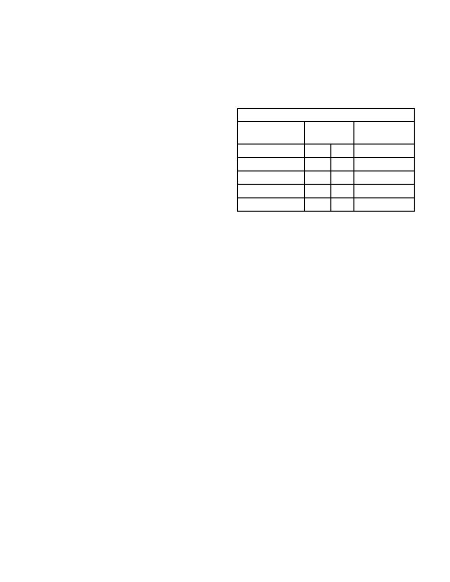
made are shown on the following chart:
to control/convert power developed by the engine
and supply power to drive the hydraulic pumps, and
Shift Points at MPH/KPH
motive power to the axles. The transmission/torque
Gear Up-Shift
Speed
Gear Down-Shift
converter is a single assembly mounted directly onto
MPH ! KPH
the engine. It provides six sequential, power shifted
speeds.
Torque from the transmission/torque
1st to 2nd
2nd to 1st
5
8
converter is transferred as driving power for the
2nd to 3rd
3rd to 2nd
7
11
axles via drive shafts connected between them.
3rd to 4th
4th to 3rd
12
19
4th to 5th
5th to 4th
17
28
CONVERTER LOCKUP
5th to 6th
6th to 5th
36
57
The torque converter is equipped with automatic
lock-up capabilities and activates at a predetermined
rpm and torque level.
Stepping of changes should be progressive. No
attempt should be made to down or up-shift 2 gears
This capability allows the crane to operate more
or more at any one time.
effic-iently when driven and is useful on downhill
grades and during deceleration where the additional
It is not always necessary to start crane in 1st gear.
braking effect from the engine is advantageous.
Up to 3rd gear may be used when starting on
reasonably level terrain.
OPERATION OF POWERSHIFT TRANSMISSION
To avoid hard shifting, when operating in the manual
mode, the road speeds at which a shift should be
THEORY OF OPERATION
The transmission and torque converter function
spool works against the spring until a port is exposed
together and operate through a common hydraulic
along the side of the bore. This sequence maintains
system. Therefore, it is necessary to consider both
the pressure needed for control and assures proper
units in discussing operation.
system operation.
With the engine running, the converter charging
After entering the converter housing, the oil is
pump draws oil from the transmission sump through
directed through the reaction member support, to the
the removable oil suction screen and directs it
converter blade cavity, then exits in the passage
through the pressure regulating valve and oil filter.
between the turbine shaft and reaction member
support. The oil then flows out of the converter to
The pressure regulating valve maintains the
the oil cooler. After leaving the cooler, the oil is
pressure used to actuate the directional and speed
returned to a fitting on the transmission, and directed
clutches which control the transmission.
This
through a series of tubes and passages where it
requires a small portion of the total volume of oil
used in the system. The remaining volume of oil is
then gravity drains to the transmission sump.
directed through the torque converter circuit to the oil
cooler, then returned to the transmission. The
regulator valve consists of a hardened valve spool
operating in a closely fitted bore. The valve spool is
spring loaded to hold the valve in a closed position.
When the specified pressure is achieved, the valve


