TM 5-3810-307-24-1-1
MAINTENANCE
DRIVE LINES
Removal
CAUTION
Mark the universal(s) so they can be installed as removed, otherwise severe
drive line vibration may occur.
a.
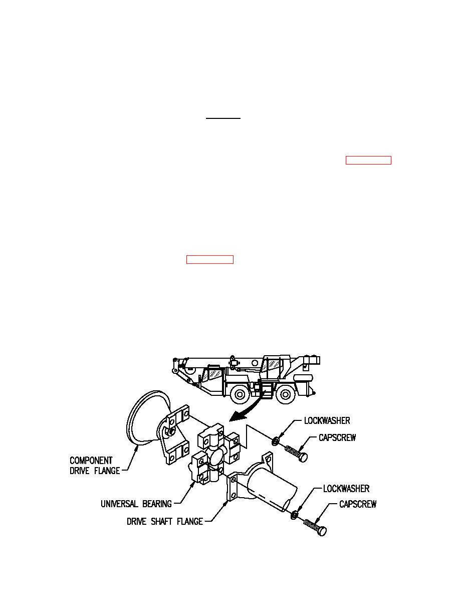
Scribe a match mark across drive shaft universal bearings and component drive flanges (Figure 2-3-1).
b.
Support drive shaft and remove capscrews and lockwashers securing drive shaft universal bearings to
component drive flanges.
c.
Remove drive shaft from crane.
d.
If necessary, remove capscrews, lockwashers, and universal bearings from drive shaft.
Installation
a.
If removed, install universal bearings (Figure 2-3-1) on drive shaft with lockwashers and capscrews.
Torque capscrews to 90-110 lbs-ft (122-149 Nm).
b.
Position drive shaft to component drive flange aligning match marks made during removal.
c.
Secure drive shaft with lockwashers and capscrews. Torque capscrews to 90-110 lbs-ft (122-149 Nm).
Lubrication
Lubricate the universal joints in accordance with Lubrication Chart, Chapter One, Section 4.
2-3-6


