TM 5-3810-307-24-1-1
Four Wheel Drive
maintenance personnel to help troubleshoot the
system. During initial power-up, the unit will self test
The DRIVE AXLE selector switch on the front
and the LEDs will light for about one second. After
console is used to select two or four wheel drive.
that they will light to reflect the following faults:
When two wheel drive is selected, there is no input.
When four wheel drive is selected, battery voltage is
RED LED - Illuminates if there is a problem
input indicating four wheel drive selection.
internal to the APC 100 control unit. In this
case the APC 100 enters the fail-safe mode
Throttle Position
and all outputs are switched off.
An idle switch inputs battery voltage when the throttle
YELLOW LED - Illuminates when engine or
is in the idle position (switch closed). When the
turbine speed reads zero. This LED will
throttle is moved from the idle position the idle switch
remain lit until the engine is started.
opens and the full throttle position switch closes
inputting battery voltage to indicate throttle position.
GREEN LED - Illuminates when an improper
gear selection pattern is input by the shift
Gear Selection
selector.
A switch matrix of five wires decodes the gear
Two Wheel Drive Solenoid
selector position. The five wires are switched
between open and battery voltage.
If four wheel drive input voltage is present, the APC
100 will automatically switch to two wheel drive when
Lockup Request
the transmission reaches F4 or R5. The four wheel
drive voltage opens the 2WD interlock relay allowing
The lockup switch closes and inputs battery voltage
the 2WD load out relay to close and battery voltage
to enable converter lockup when conditions permit.
is output to switch the vehicle to two wheel drive.
An open switch disables lockup.
Lockup Solenoid
Turbine Speed
The torque converter lockup output switches
The turbine speed is monitored by a pulsed signal
between battery voltage and zero depending on the
that is generated by a speed sensor in the same
engine and turbine speed input ratio. The output is
manner as the engine speed sensor.
connected to a solenoid and is energized when
lockup is engaged.
OUTPUTS
Overspeed and Low Clutch Pressure Indicator
Diagnostic LEDs
This output lights a LED on the front console. The
LED will illuminate (steady) if a gear is selected that
would cause an overspeed condition and will go out
when rpm drops to a speed allowing the selection.
The LED will blink rapidly should a turbine failure
occur. The APC must be reset to clear this
condition. The LED will blink slowly if low clutch
pressure is detected for more than five seconds.
LED will go out when sufficient pressure returns.
Shift Solenoids
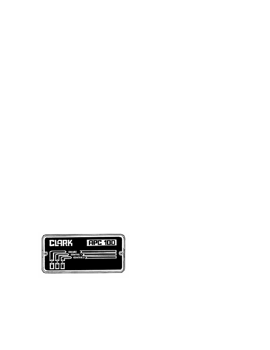
Figure 2-3-6. Diagnostic LEDs
The shift solenoids output switch between battery
voltage and zero as associated shift speeds are
There are three diagnostic LEDs (Light Emitting
reached. The output energizes the appropriate shift
Diodes), under a cover, on the top of the APC 100
solenoid when the output is switched on.
control box. These lights can be used by
2-3-17


