TM 5-3810-307-24-1-1
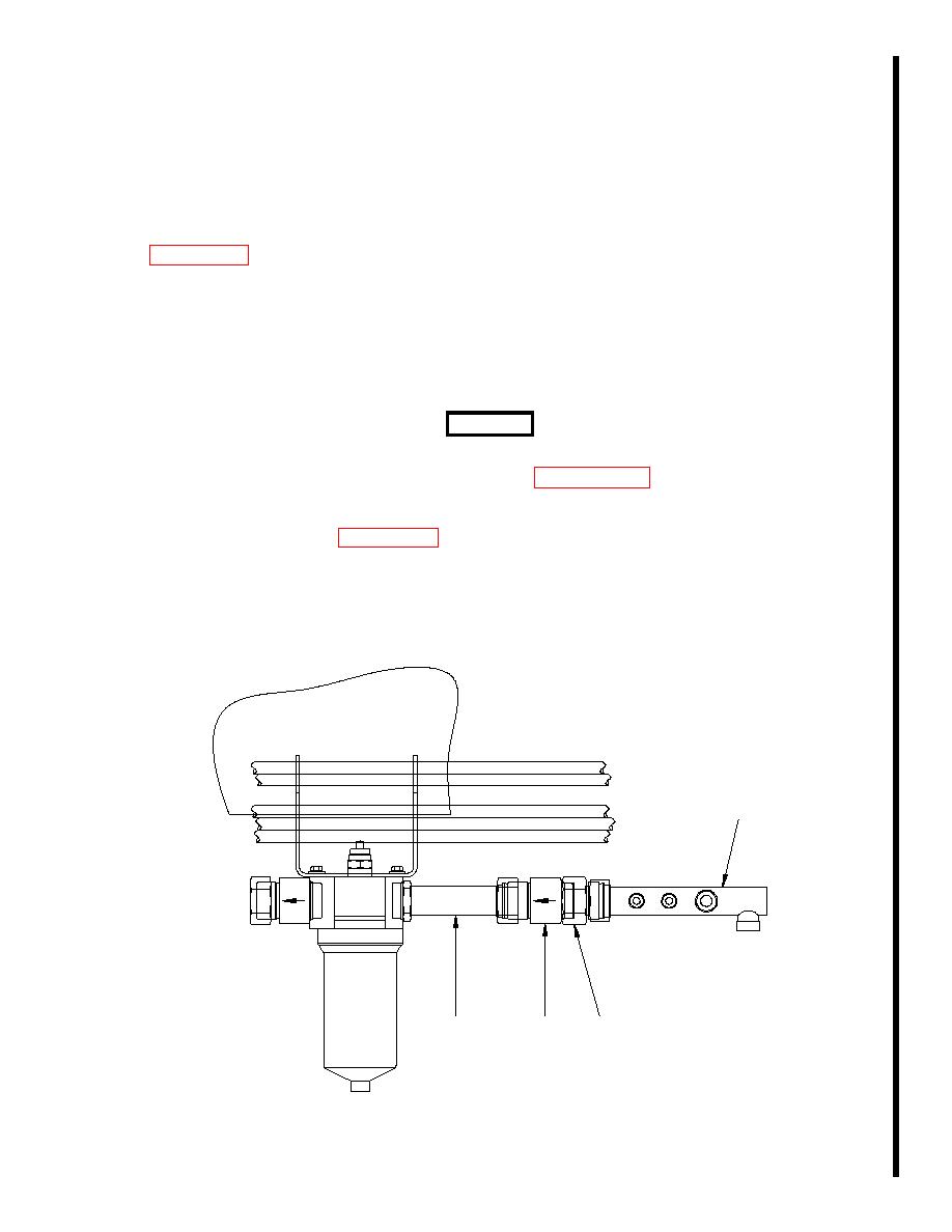
STEERING SYSTEM FILTER CHECK VALVE
Removal
a.
Ensure battery disconnect switch is in OFF position.
b.
Use tie wraps to secure hydraulic hoses out of the way to clear a path to the check valve (3,
c.
Get set to contain any hydraulic fluid contained in the four hydraulic lines connected to manifold
(1). Then tag and disconnect the four hydraulic lines connected to manifold (1).
d.
Remove manifold (1) and adapter (2).
e.
Remove check valve (3) from straight adapter (4).
Installation
WARNING
Ensure check valve is installed with the arrowhead pointing toward
the filter element as illustrated in Figure 2-5-9 to prevent
catastrophic damage to equipment or injury to personnel.
a.
Install new check valve (3, Figure 2-5-9) on straight adapter (4).
b.
Install adapter (2) and manifold (1).
c.
Connect four hydraulic lines to manifold (1) as tagged. Remove tags.
d.
Remove tie wraps securing hydraulic hoses out of the way.
1
2
4
3
2-5-23/(2-5-24 Blank) C-1


