TM 5-3810-307-24-1-2
1. GENERAL FLOWCHART AND DRAWINGS
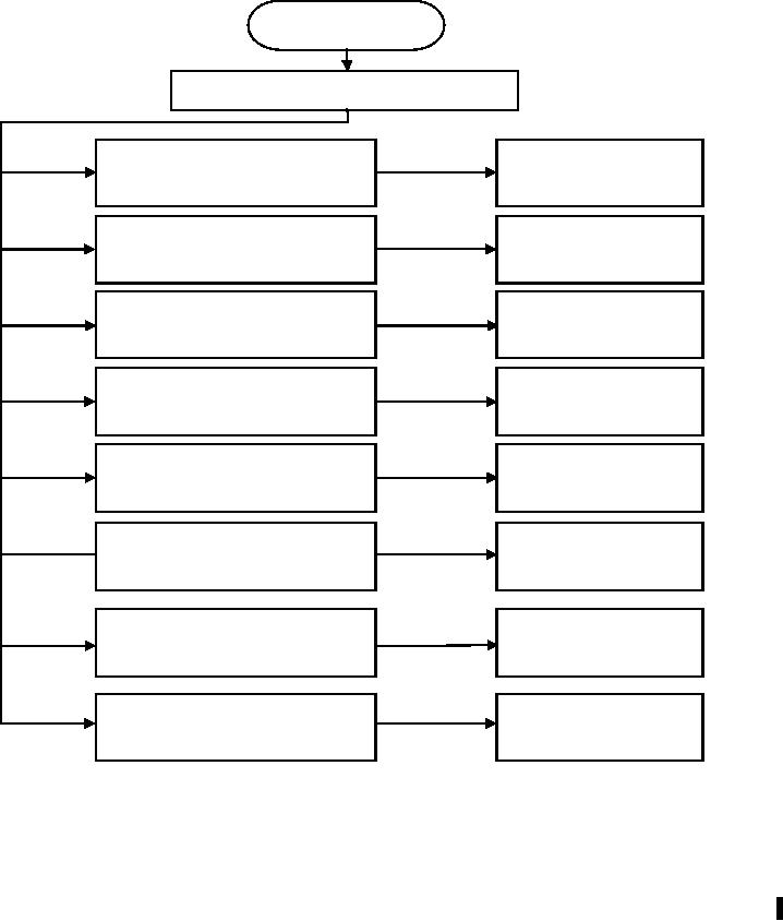
This section explains how to handle a problem that may arise with the PAT Load Moment
Indicator System-PAT DS350. The procedures are given in flowchart form for the following
sections. Start with the general flowchart below which will guide you to one of the detailed
flowcharts shown in Sections 2 through 9. The drawings in this section will be referenced in
the troubleshooting flow charts, Sections 2 through 9.
START
What's Wrong?
Lever Lockout Activated
Go to Section 2
Broken Length Cable
Go to Section 3
No display
Go to Section 4
Anti-Two Block Problem
Go to Section 5
Length Displayed Incorrect
Go to Section 6
Load Displayed Incorrect
Go to Section 7
Bad Data Transfer/Interference
Between Central Unit and
Go to Section 8
Console
Error Code Displayed
Go to Section 9
Change-1 G-7

