
TM 5-3810-300-24&P-3
2.7.1
LIMITING SPEED GOVERNOR
2. Disassemble the governor control housing:
a. Place the control housing in a soft jawed vise.
b. Remove two bolts (53), Fig. 9, and withdraw the high
speed spring retainer cover (51).
c. Loosen the lock nut (49) with tool J 5345-5. Remove
the high speed spring retainer (50), idle adjusting
screw (55), high speed spring (48), spring plunger
(44), low speed spring (46), spring seat (45), and
spring cap (47) as an assembly.
d. Remove the spring retainer (25) and washer, then lift
the differential lever (23) from the pin of the operating
shaft lever (27).
Fig. 2 Typical Limiting Speed Governor Mounting
Disassemble Governor
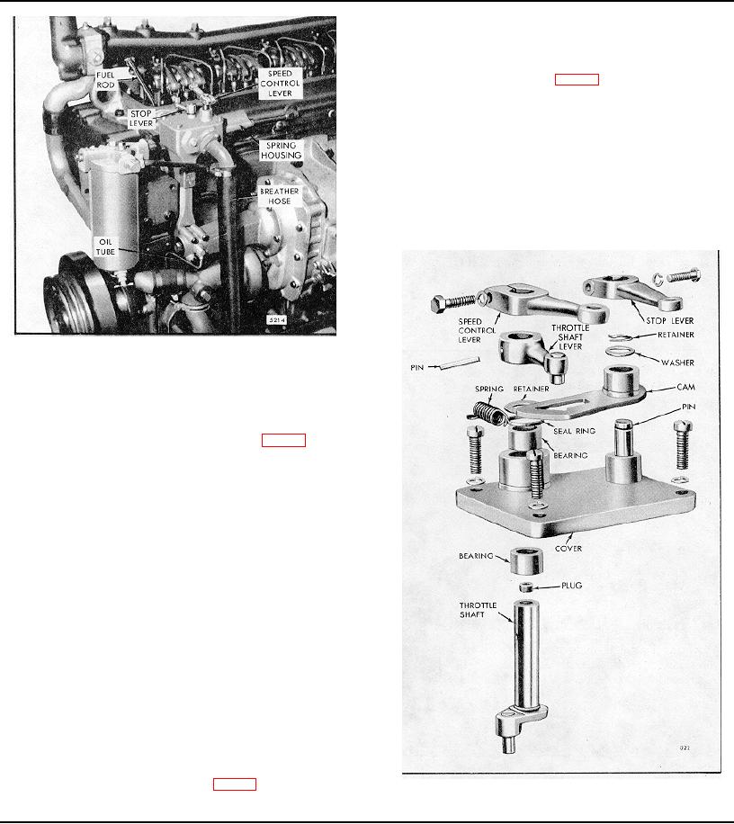
1. Disassemble governor cover:
a. Remove the plug from the throttle shaft (Fig. 3).
b. Loosen the speed control lever bolt, and lift the speed
control lever from the throttle shaft.
c. Remove the tapered pin from the throttle shaft lever.
Lift the lever and the seal ring retainer from the
throttle shaft. Withdraw the throttle shaft from the
cover.
d. Remove the cam retainer and plain washer from the
cam pin. Lift the cam and the stop lever off the pin.
e. Remove the seal ring from the governor cover.
f. Wash the cover assembly (containing needle
bearings) thoroughly in clean fuel oil and inspect the
needle bearings for wear or damage. If the bearings
are satisfactory for further use, removal is
unnecessary.
g. If needle bearing removal is necessary, place the
inner face of the cover over the opening in the bed of
the press. Place remover J 21967 on top of the
bearing and under the ram of the press; then press
both bearings out of the cover (Fig. 4).
Fig. 3 Governor Cover Details and Relative Location of Parts
Page 199

