
TM 5-3810-300-24&P-3
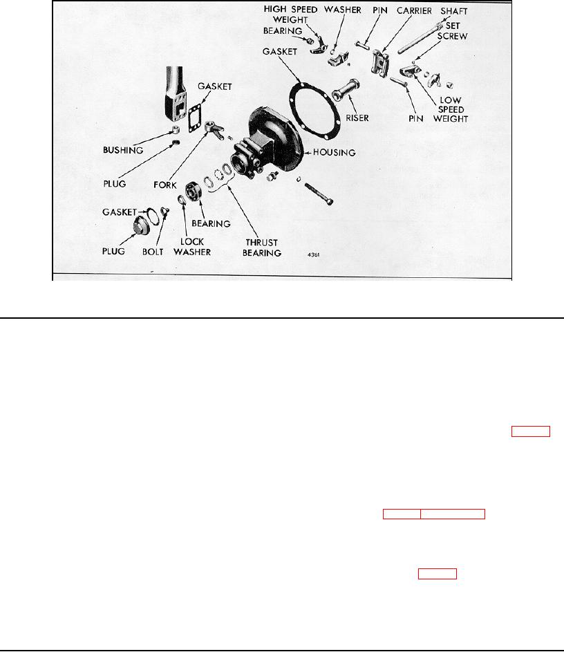
Fig. 4 - Fuel Modulating Governor Weight Housing Details and Relative Location of Parts
2.7.1.1 LIMITING SPEED GOVERNOR
4. Remove the idle speed adjusting screw (55), also
the modulating spring adjusting screw (100).
10. Remove the lock screw, lock washer and plain
washer holding the upper bearing (30) in the control
5. Remove modulating spring plunger retainer ring
housing.
(109) from high speed spring plunger with sharp-nosed
pliers.
11. Loosen the operating fork set screw, if used.
6. Remove the modulating spring plunger (108),
12. Support the control housing as shown in Fig. 6 in
modulating spring (107) and modulating spring seat
Section 2.7.1. Press the operating shaft (26) from the
(106) from inside the high speed spring plunger.
operating fork (73) with a brass rod. Withdraw the
operating shaft (26), operating lever (27), and bearing
7.
Remove the spring retainer (25) and washer.
(30) as an assembly from the control housing.
Lift the differential lever (23) from the pin on the
13. Support the operating shaft and lever on bed of
operating shaft lever (27).
press as shown in Fig. 7 Section 2.7.1. Press the shaft
from the operating lever and bearing with a brass rod.
8. Remove the special screw (94) retaining the torsion
spring (97) to the differential lever, then remove the
Disassemble Governor Weight Housing
spring from the screw.
1. Place weight housing (Fig. 4) in a soft jawed vise.
9. Remove the expansion plug out of the lower end of
Remove the plug and gasket.
the control housing.
2. Straighten the tang on the lock washer and remove
the bearing retaining bolt.
Page 210

