TM 10-1670-298-20&P
(2) Replacement. A parachute connector link assembly, regardless of the type, which is damaged beyond
repair will be replaced with a serviceable L-bar parachute connector link assembly from stock and the
following procedures:
(a)
Using a suitable sized flat-tip (common head) screwdriver (Item 5, Appendix B), remove the two
locking screws from the ends of a replacement L-bar parachute link assembly and disassemble the
link.
(b)
Using a suitable sized flat-tip (common head) screwdriver (Item 5, Appendix B), remove the two
locking screws from the damaged original parachute connector link assembly. Disassemble the
link assembly, using a link separator (Figure 2-6), if necessary. If the connector link contains
suspension lines, insure the lines are not allowed to slide off the damaged link during the
disassembly process.
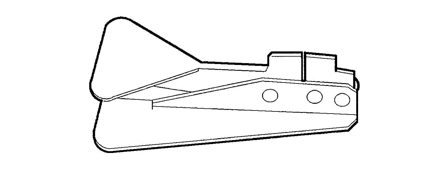
Figure 2-6. The Parachute Connector Link Separator
(c)
As applicable, position an L-bar of the replacement link assembly adjacent to the disassembled
original link assembly and slide the suspension lines from the damaged link onto the replacement
link L-bar.
(d)
If required, pass the remaining L-bar of the replacement link through the attaching loop of the
adjoining component
(e)
Fit the replacement link L-bars together and insure L-bar leg engagement by tapping the end of
each L-bar with a phenolic mallet
(f)
As applicable, trace the suspension lines from the connector link assembly to the canopy skirt to
insure the lines are properly installed and in the correct sequence.
(g)
Reinstall the two locking screws removed in (a) above and tighten each screw using a suitable
sized flat-tip (common head) screwdriver (Item 5, Appendix B).
2-19