(2) Visually inspect all parts for excessive
wear, burs, stripped threads, or other damage. Inspect
push-pull controls for freedom of movement.
(3) Repair by replacing defective components
or mounting hardware.
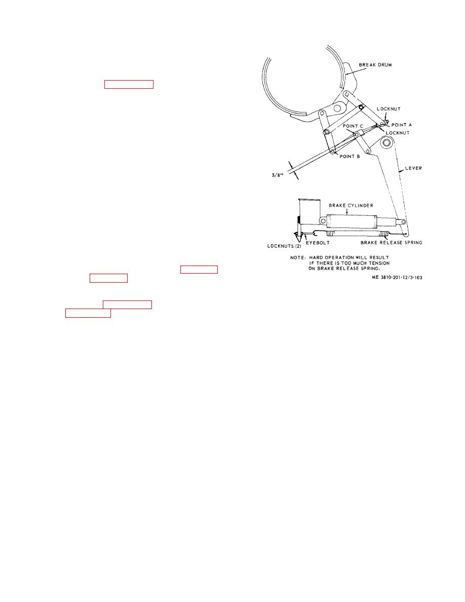
c. Swing Brake Linkage Adjustment.
(1) Refer to figure 3-103, adjust locknuts on
either side of point A so that lever touches edge of slot
in the side stand.
(2) Lay a straight edge from point A to point
B. Point C should be 5/8 inch nearer brake drum. This
will keep linkage from "toggling in". When toggling in
does occur, the brake will not release when pressure on
hydraulic cylinder is released.
(3) Adjust two locknuts so that alinement of
points A, B, and C are maintained as described in (1)
and (2) above.
(4) Adjust two locknuts on eyebolt at brake
release spring until there is just enough tension on
spring to release brake when hydraulic pressure is
released.
3-123. Hydraulic Clutch and Brake Cylinders and
Linkage
a. Removal and Installation.
(1) Position container to receive fluid, then
disconnect hydraulic line at clutch cylinders (fig. 3-104)
or brake cylinder (fig. 3-105), and plug or cover end of
Figure 3-103. Swing brake linkage adjustment.
line and port of cylinder to prevent contamination of
hydraulic system.
(2) Visually inspect linkage and mounting
(2) Refer to figure 3-104 and remove clutch
hardware for distortion, wear, burs, or stripped threads.
cylinder, or figure 3-105 to remove brake cylinder.
Inspect hydraulic cylinder for signs of leakage or
(3) Remove remaining cylinders in a similar
deterioration of end cups.
manner.
(3) Repair by replacing defective linkage
(4) Install in reverse order.
parts, mounting hardware, and a leaking or defective
b. Cleaning, Inspection, and Repair.
hydraulic cylinder.
(1) Clean all parts in an approved cleaning
solvent and dry thoroughly.
3-115


