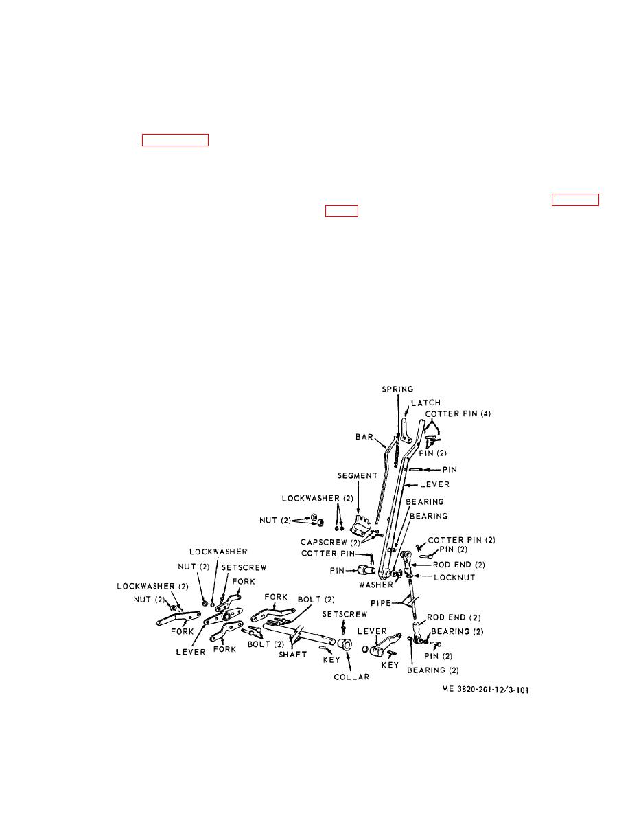
(2) Loosen locknut at rod end then turn pipe
(3) Minor adjustment to foot pedals are made
clockwise to shorten, counterclockwise to lengthen.
by connecting links to pedals in either the front or rear
(3) When length is satisfactory, tighten
holes in lower portion of pedal. Push rod adjustment at
locknut up to rod end and connect rod end to lever by
pedal compensator are made in a manner similar to that
installing pin and securing with cotterpin.
described in (2) above.
3-122. Swing Brake Hydraulic Control and Linkage
3-121. Swing and Propel Shifter Lever and Linkage
a. Removal and Installation.
Adjustment
(1) Refer to figure 3-101 and remove swing
a. Swing Brake Hydraulic Control, Removal and
propel shifter lever and linkage.
Installation.
(2) Install in reverse order.
(1) Remove side panel from instrument
b. Cleaning, Inspection and Repair.
control stand.
(1) Clean all parts in an approved cleaning
(2) Position a suitable container under control
solvent and dry thoroughly.
stand to receive hydraulic fluid, then refer to figure 3-
(2) Visually inspect all parts for excessive
wear, bends, breaks, or other defect. Inspect mounting
swing brake hydraulic control.
hardware for burs or stripped threads.
(3) Install in reverse order.
(3) Repair by replacing damaged parts or
defective hardware.
Note.
c. Adjustment. Adjust the linkage for positive
Remove
remaining
hydraulic
engagement of the swing or propel jaw clutches by
controls in a similar manner.
adjusting the overall length of pipe and two rod ends as
follows:
b. Cleaning, Inspection, and Repair.
(1) Remove cotterpin and pin that connects
(1) Clean all parts in an approved cleaning
rod end clevis to lever.
solvent and dry thoroughly.
Figure 3-101. Swing and Propel shifter level and linkage, removal and installation.
3-113


