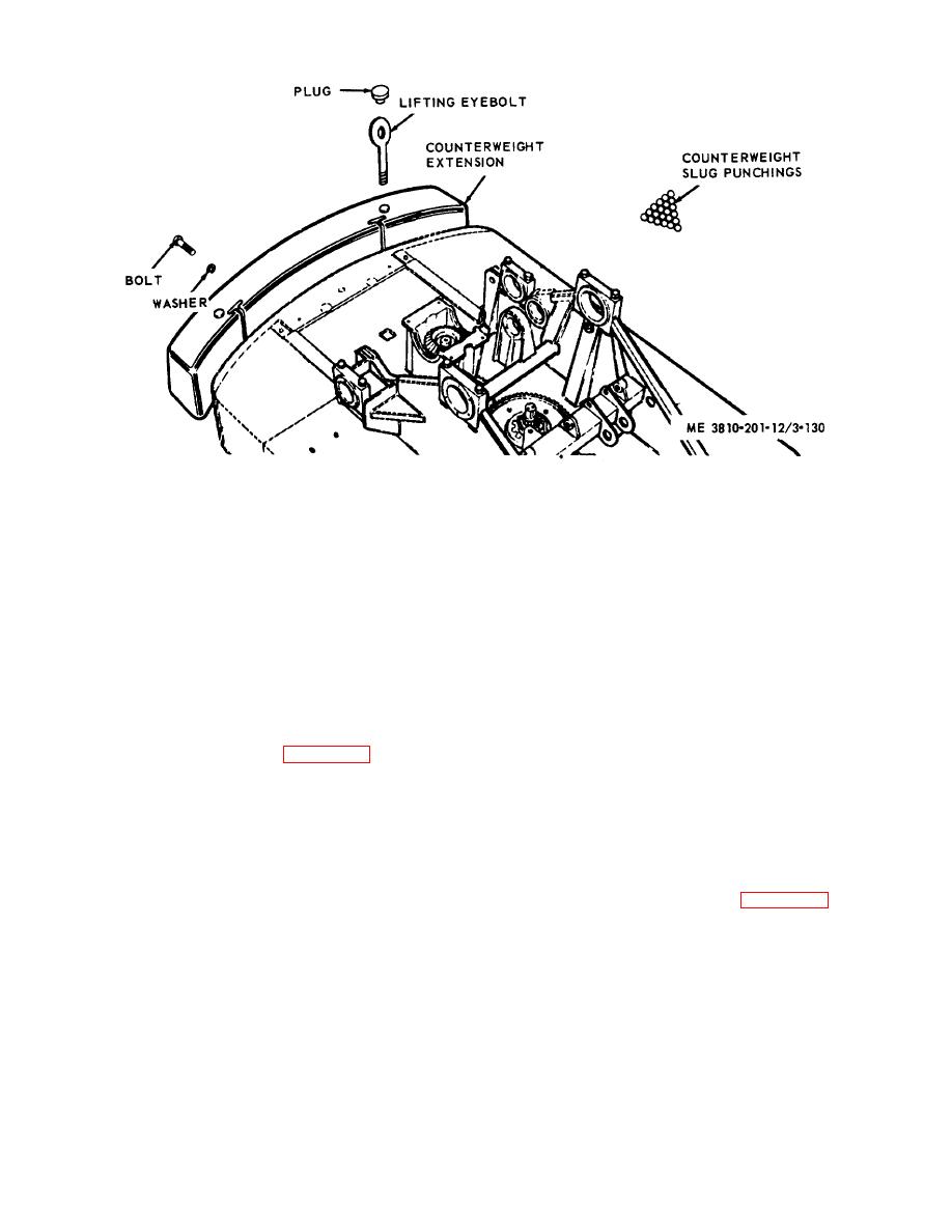
Figure 3-130. Counterweight extension, removal and installation.
counterweight extension, and install two lifting eyebolts
The counterweight consists of slug punchings which are
in counterweight.
stored in compartments of revolving frame, and the
(3) Secure lifting hooks in lifting eyebolts,
extension, which mounts on rear of revolving frame.
take up slack, then remove bolts and washers.
Purpose of counterweight distribution is to offset
(4) Lift extension up and off revolving frame,
extended weights of front end attachment and load.
and move to a suitable storage area.
Slug punchings are not ordinarily removed from
b. Installation.
revolving frame.
(1) With a suitable lifting device, lift
counterweight extension, move to rear of crane-shovel
3-163. Counterweight Extension
basic unit and position it for installation.
a. Removal.
(2) Install bolts and washer to secure
(1) Position lifting device capable of lifting
extension to frame, then remove lifting hooks.
10,000 lbs at rear of crane-shovel unit.
(3) Remove two lifting eyebolts, then install
(2) Remove two plugs (fig. 3-130) from
plugs in bolt holes.
Section XXII. CAB, PANELS, DOORS, WINDOWS, AND SEATS.
3-164. General
3-165. Door Handrail (Grip)
The cab of the crane-shovel basic unit is manufactured
a. Removal and Installation.
of sheet metal sections, panels, doors, and window
(1) Remove two nuts (fig. 3-131) and two
frames, which are bolted to one another and to the
washers, then remove handrail from cab.
revolving frame. Any part of the cab can be removed
(2) Remove the two remaining nuts from
for repair, or in sections to provide access to machinery
handrail.
components that require repair or adjustment. Panels
(3) Install in reverse order.
and doors on winterized units have a slight difference in
b. Cleaning, Inspection, and Repair.
configuration, but are removed and installed in a similar
(1) Clean handrail in an approved cleaning
manner.
solvent and dry thoroughly.
3-141


