1
Capscrew (6 rqr)
10
Sidestand
2
Shaft end cap
11
Idler gear
3
Main hoist shaft
12
Collar
4
Bolt (2 rqr)
13
Lockwasher (2 rqr)
5
Nut (2 rqr)
14
Capscrew (2 rqr)
6
Lockwasher (2 rqr)
15
Nut (4 rqr)
7
Bolt (2 rqr)
16
Bolt (4 rqr)
8
Bearing cap (2 rqr)
17
Outboard bearing support
9
Nut (2 rqr)
18
Outboard bearing bracket
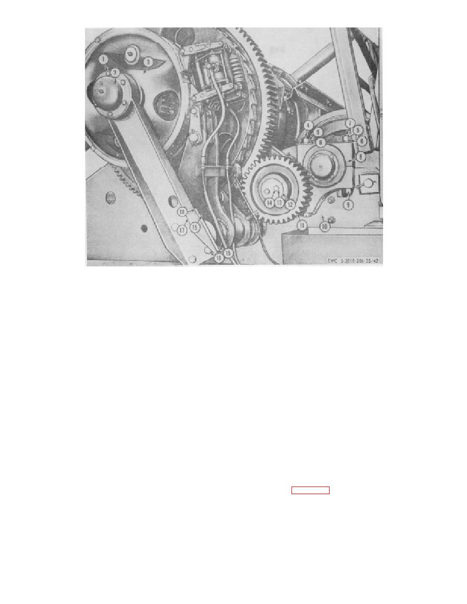
Figure 4-5. Main hoist shaft, left side installed view.
(8) Remove shims (21) and mark for order of
(11) Install jackshaft by
reinstallation.
reversing the procedure to steps (10)
(9) Position sling around shaft, attach to a
through (1) above.
suitable lifting device (another crane if available), then lift
vertically until shaft is clear of all obstructions.
NOTE
(10) Swing the shaft clear of the revolving frame;
Adjust swing clutches and swing
transport it to a suitable area for further disassembly,
clutch operating mechanism before
then lower it to rest on cribbed wooden blocks or other
operation (TM 5-3810-201-12).
suitable support.
b. Disassembly.
CAUTION
Use extreme care while lowering
(1) Remove drive sprocket (TM 5-3810 201-12)
jackshaft into position in sidestands
then refer to figure 4-7 and disassemble in the following
to avoid damage to gears and
order:
(2) Remove eight capscrews (65), lockwashers
sprockets.
(62), adapter ring (61), gasket (59), adapter ring (60) and
gasket (59).
4-7


