installed in step (1) above; install another bearing (23) up
(21) Heat bearing (51) and slide on shaft (38)
snug against spacer (33), then install spacer (30).
until tight against retainer (50), slide bearing housing
(18) Repeat steps (6) through (13) above on
(52), seal (53), three shims (54); spacer (55), and gasket
right end of shaft (38).
(56) on shaft (38). Secure with adapter ring (57), six
(19) Slide spacer (40) with large diameter
bolts (58), lockwashers (49), and nuts (48).
towards center on shaft (38) until tight against washer
(22) Position gasket (59), adapter ring (60),
(12).
gasket (59), and adapter ring (61) on gear case, then
(20) Install bushing (47) in bearing retainer (50)
secure with eight lockwashers (62) and capscrews (65).
and install fitting (46) in bushing (50), then install retainer
(50) on small diameter of spacer (40).
(23) Install drive sprocket (TM 5-3810-201-12).
Section VI. INTERMEDIATE HOIST SHAFT
(3) Support gear (11, fig. 4-6) on right hand end
4-12. General
of shaft.
(4) Remove nuts (8) and lockwashers. Remove
The intermediate hoist shaft is the short shaft located on
locking plate (9) and bearing retainer (10).
left side of revolving frame, between jackshaft and drum
(5) Remove bearing locknut (25, fig. 4-8) and
(main hoist) shaft. The gear on right end of intermediate
lockwashers (25) from end of shaft (15).
hoist shaft meshes with gear on jackshaft, while the gear
(6) Remove two capscrews (14, fig.
on left end meshes with gear on drum (main hoist) shaft.
lockwashers (13), and collar (12) from left end of shaft
(15, fig. 4-8).
4-13. Intermediate Hoist Shaft
(7) Remove bearing retainer from housing.
a. Removal.
(8) Remove shaft (15) and outside gear (11, fig.
4-5), from left hand side as a unit. Remove remaining
(1) If front end attachment is installed, lower
gear (11, fig. 4-6) from revolving frame.
boom to reset on cribbing, and assure that engine is
stopped.
b. Disassembly.
(2) Remove hoist gear guard (TM 5-3810-201-
12).
(1) Remove gear (4, fig. 4-8) from left end of
shaft (15).
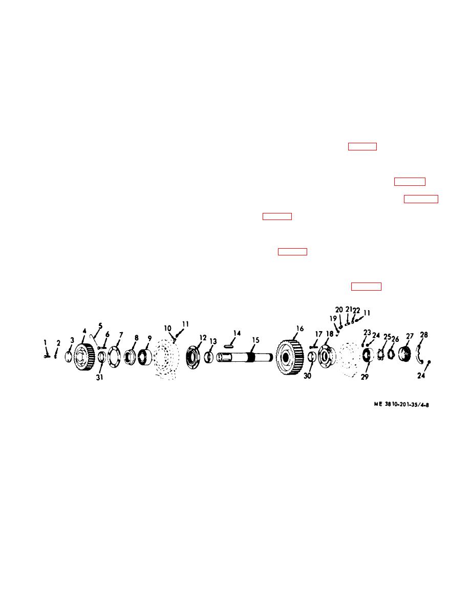
1 Capscrews (2 rqr)
12
Bearing retainer
23
Lockwasher (5 rqr)
2 Lockwasher (2 rqr)
13
Spacer
24
Nut (5 rqr)
3 Collar
14
Key (2 rqr)
25
Key Washer
4 Spur gear
15
Shaft
26
Nut
5 Wire
16
Spur gear
27
Bearing retainer
6 Screw (6 rqr)
17
Capscrews (5 rqr)
28
Lock plate
7 Retainer plate
18
Housing
29
Bearing
8 Bearing retainer
19
Pipe nipple
30
Spacer
9 Bearing
20
Elbow
31
Spacer
10 Pipe bushing
21
Pipe nipple
11 Fittings (2 rqr)
22
Pipe coupling (2 rqr)
Figure 4-8. Intermediate hoist shaft, exploded view.
4-11


