in numerical sequence, and starter motor is removed.
Install in reverse order.
(4) Remove brush from guide by pulling
outward on brush lead.
b. Cleaning and Inspection.
(5) Install new brush by first lifting outward on
brush spring.
(1) Clean all parts with a rag dampened in an
approved cleaning solution and dry thoroughly. Blow dust
(6) Insert brush into guide, push it down into
from brush area with low pressure compressed air.
contact with commutator, and let spring down on top of
brush.
(2) Visually inspect mounting hardware for
wear or stripped threads. Replace defective hardware or
(7) Seat brush so it has perfect surface contact
starter motor. Repair by replacing defective brush set (c
with commutator.
below).
Note
Brushes can be seated perfectly by
drawing a piece of 00 grade sandpaper
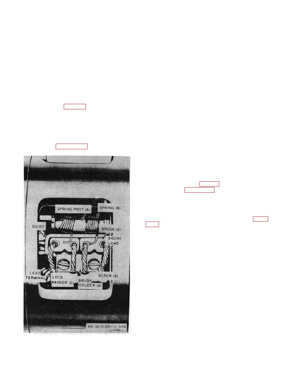
c. Starter Motor Brush Replacement.
between commutator and brush and
(1) Remove starter motor (a above).
against brushholder. Sand only as
(2) Refer to fig. 3-64 and remove items (19)
much as is necessary to obtain a
and (20).
perfect brush fit. Blow the sand and
carbon dust out of starter motor with
Note
low pressure compressed air.
Remove and replace one brush at a
(8) Pull brush outward 1/4 inch and then allow spring
time, until set of eight is replaced.
to push it back down into guide. Repeat this step as often
as necessary to assure brush is free in guide and will not
(3) Refer to figure 3-65,
remove
screw
and
bind.
lockwasher from brushholder.
(9) Connect brush cable terminal to brushholder with
screw and lockwasher.
(10) Install remaining brushes by repeating steps (3)
through (9) for each brush.
(11) Position inspection band on starter and secure
with two screws and nuts (fig. 3-64).
(12) Refer to figure 3-64 and install starter by
reversing numerical sequence (18) through (13), then (2).
3-82. Relay Solenoid (Starter)
a. Removal and Installation.
(1) From engine model 687C-18-ES. Refer to figure
sequence, to remove relay solenoid. Install in reverse
order.
(2) From engine model D333TA. Remove or install
in a manner similar to that' described in (1) above.
b. Cleaning, Inspection and Repair.
(1) Clean relay solenoid with a rag dampened in an
approved cleaning solvent and dry thoroughly.
(2) Visually inspect mounting hardware for excessive
wear or stripped threads, electrical leads for loose
terminals, bare wire, or frayed insulation, and test relay
for proper operation by placing source-of 24 vdc power
across terminals and listen for solenoid movement.
(3) Repair by replacing defective hardware, electrical
lead, or defective relay solenoid.
3-83. Receptacle (Slave) Electrical Connector
a. Removal and Installation.
Figure 3-65. Starter motor brush replacement.
3-75


