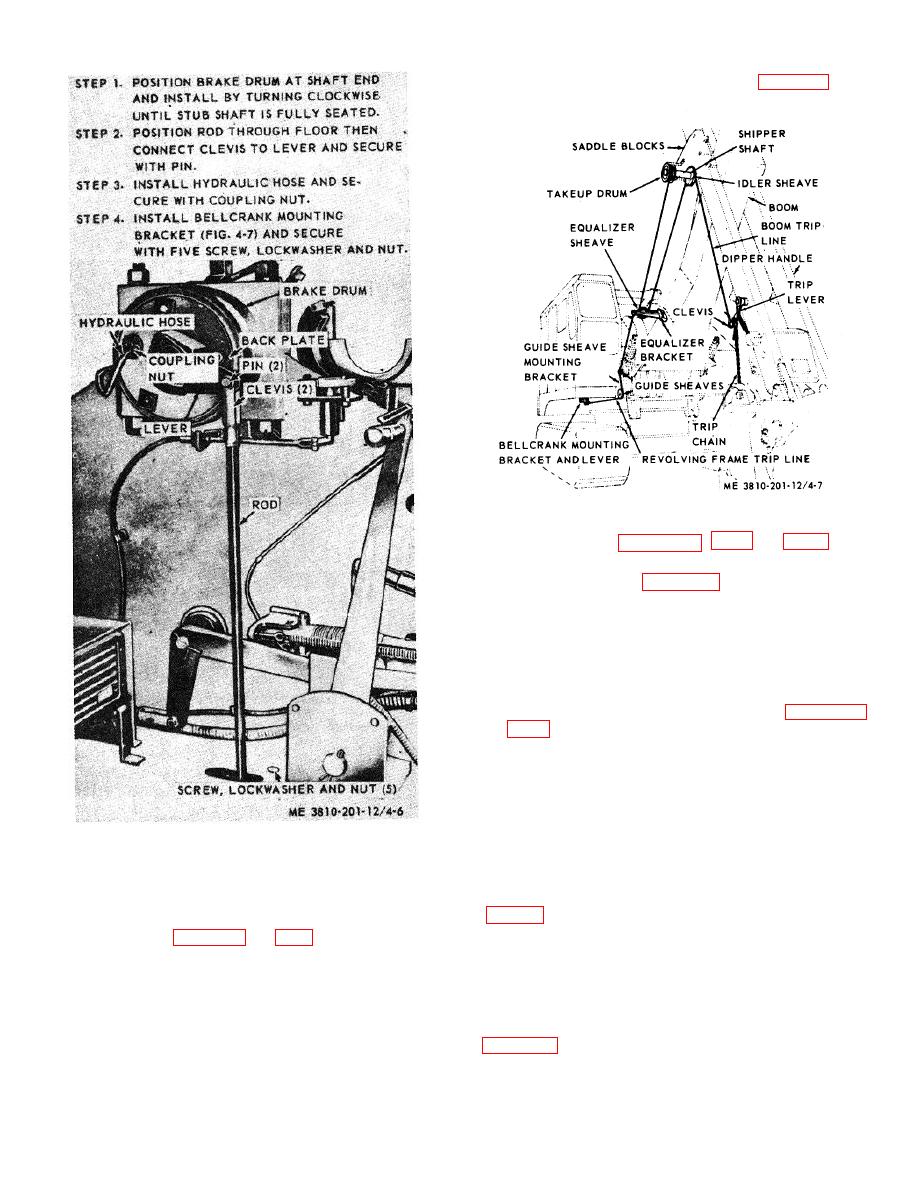
(1) Install dipper trip lever (fig. 2-23) and
secure
with
pin
to mounting bracket. Install hydraulic compensator and
line to main header (paras 3-111, 3-112 and 3-113).
(2) Refer to figure 4-6 and install dipper trip
mechanism.
(3) Install bellcrank mounting bracket under
revolving frame, and guide sheave mounting bracket on
revolving frame at boom foot (fig. 4-7) .
(4) When shovel front end attachment is
installed, install revolving frame trip line.
(5) Adjust dipper trip mechanism (paras 3-33
and 3-34).
Note.
The above procedure assumes that
shovel tripping mechanism is
installed on boom of shovel front
end attachment.
Figure 4-6. Dipper trip mechanism, removal
c. Removal. The entire dipper trip mechanism may
or installation.
be removed for replacement or repair as follows:
(1) Dipper trip clutch mechanism removal.
izer bracket on boom, through guide sheaves on bracket
(a) Remove pin from clevis at lever
mounted on revolving frame at boom foot to bell crank
lever mounted. underneath revolving frame. When
(b) Lossen coupling nut and remove
properly adjusted (para 3-33 and 3-34), dipper is tripped
hydraulic hose from wheel brake cylinder.
when dipper trip lever (fig. 2-93) is actuated.
(c) Grasp brake drum firmly and turn
counterclockwise to remove mechanism from end of
b. Installation.
main hoist 6rum shaft.
(2) Disassembly and reassembly. Refer to
in numerical sequence. Assemble in reverse order.
4-7


