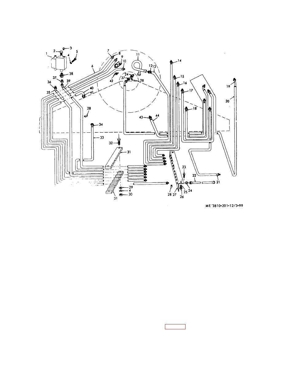
NOTE:
WHEN A LINE IS REMOVED, MARK ITS FITTINGS AND POSITION ON THE REVOLVING
FRAME. PLUG OR COVER ENDS OR PORTS TO PREVENT CONTAMINATION OF
HYDRAULIC SYSTEM.
1
Hydraulic tank
12
Tubing
23
Screw (2)
84 Tubing
2
Fill plug
13
Conduit
24
Adapter (22)
35 Tubing
3
Fluid level plug
14
Tubing
25
Lockwasher (2)
36 Nut connector (80)
4
Lockwasher (2)
15
Tubing
26
Nut (2)
87 Adapter (2)
o
Capscrew (2)
16
Tubing
27
Bracket
88 Shutoff cock
6
Conduit
17
Tubing
28
Spring clip (22)
39 Conduit
7
Tubing
18
Tubing
29
Flatwasher (2)
40 Conduit
8
Tubing nut
19
Tubing
30
Nut
41 Tubing
9
Bracket
20
Conduit
31
Clamp
42 Clamp
10
Tubing
21
Tubing
32
Capscrew
43 Tubing
11
Home
22
Hose (10)
33
Conduit
44 Conduit
Figure 3-86. Hydraulic hose, lines, tubes, and fittings, removal and installation.
lever stand and its components, therefore, these
(2) Visually inspect compensator for external
instructions will cover individual component removal.
damage or excessive wear, burs, or stripped threads on
mounting hardware, or deterioration of boot on push rod.
b. Lever and Linkage Removal and Installation
(3) Repair by replacing damaged hardware,
(1) Remove upper and lower cover plates
defective boot or compensator.
from lever stand.
(2) Remove boom hoist hydraulic control
3-113. Levers and Linkage (Lever Stand)
handle (fig. 2-23) from boom hoist lever, and applicable
a. General. Normal servicing of this equipment
(raise and lower) compensator
win not require complete removal or disassembly of the
3-93


