TM 5-3810-206-35
Manufacturer's
dimensions
Desired clearance
Maximum
Maximum
Component
and tolerance in inches
allowable
allowable
wear
clearance
Minimum
Maximum
Minimum
Maximum
CONNECTING RODS:
Connecting rod end play on crankshaft -----------------------
0.013
0.033
Connecting rod bushing-to-pin clearance---------------------
0.0015
0.0030
-----------
------------
------------
0.008
Bearing clearance -----------------------------------------------
0.002
0.0335
-----------
------------
------------
0.008
CRANKSHAFT:
End thrust---------------------------------------------------------
0.008
0.016
-----------
------------
0.020
Main bearing oil clearance--------------------------------------
0.002
0.0045
-----------
------------
------------
0.008
CAMSHAFT:
End thrust---------------------------------------------------------
0.010
0.015
-----------
------------
0.025
Bearing oil clearance--------------------------------------------
0.003
0.007
IDLER GEAR:
Gear-to-bearing oil clearance ----------------------------------
0.002
0.004
-----------
------------
------------
0.006
Bearing-to-stub shaft oil clearance ----------------------------
0.002
0.004
-----------
------------
------------
0.006
Gear thrust clearance -------------------------------------------
0.006
0.014
-----------
------------
0.020
SUPERCHARGER DRIVE:
Gear-to-bearing oil clearance ----------------------------------
0.004
0.006
-----------
------------
------------
0.010
Drive bearing-to-bearing clearance----------------------------
0.002
0.008
-----------
------------
------------
0.010
Carrier oil clearance ---------------------------------------------
0.002
0.004
Drive gear thrust clearance-------------------------------------
0.004
0.018
-----------
------------
------------
0.023
TIMING GEARS:
Backlash (gear-to-gear) -----------------------------------------
0.003
0.008
-----------
------------
0.012
INJECTION PUMP:
Shaft end clearance ---------------------------------------------
0.006
0.022
Injection lever bushing-to-pivot pin clearance ----------------
0.001
0.004
-----------
------------
------------
0.008
FUEL INJECTOR:
Fuel injector tip hole size----------------------------------------
0.028
0.031
SUPERCHARGERS:
Bearing bore------------------------------------------------------
-------------
1.3765
End thrust---------------------------------------------------------
-------------
0.005
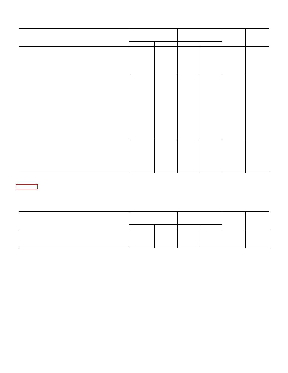
j. Generator Repair and Replacement Standards.
clearances, and the maximum allowable wear and
clearance.
Table 1-3. Generator Repair and Replacement Standards
Manufacturer's
dimensions
Desired clearance
Maximum
Maximum
Component
and tolerance in inches
allowable
allowable
wear
clearance
Minimum
Maximum
Minimum
Maximum
End play
0.003
0.010
Commutator maximum out-of-round
0.000
0.001
Mica undercut
1/32
3/64
Bearing id
0.6690
0.6693
Volts --------------------------------------------
24 vdc
k. Heater Specifications
Type control------------------------------------
Manual toggle switch
Temperature selections ----------------------
Manual
Manufacturer-----------------------------------
Hupp Corporation,
Fuel (none)-------------------------------------
Hot water
Detroit, Michigan
Model--------------------------------------------
H901-24
1-6


