TM 5-3810-206-35
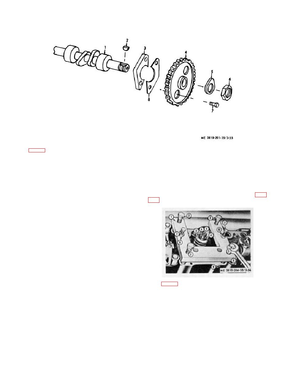
KEY to fig. 3-55:
1
Camshaft
3
Washer
5
Retainer
7
Bolt
2
Key
4
Gear
6
Nut
8
Lock
Figure 3-55. Camshaft for engine model D333TA, exploded view.
Section XV. CYLINDER HEAD, VALVE, BLOCK, AND LINERS
(5) Remove valve operating mechanism (para
3-53.
General
a. Engine Model 687C-18-ES. Each cylinder of
this engine is an independent assembly which includes a
cylinder head, liner, upper and lower jackets, and the
exhaust valve group. This design makes it possible to
service each cylinder independently.
b. Engine Model D333TA. This engine has the
conventional cylinder head, and cylinder block with
liners. The valve group is in the cylinder-head.
3-54.
Cylinder Head, Valve, and Liner (Engine
Model 687C-18-ES)
a. Removal and Installation.
(1) Drain cooling system (TM 5-3810-206-12).
(2) Drain crankcase and remove oil fill cap (TM
KEY to fig. 3-56:
5-3810-206-12).
(3) Remove valve cover and gasket (TM 5-381-
1
Cylinder head puller
6
Nut (2 rqr)
206-12).
2
Puller bolt (4 rqr)
7
Puller bolt (2 rqr)
(4) Remove fuel injectors (TM 5-3810-206-12).
3
Valve spring cap
8
Wrench
4
Exhaust valve lock (2 rqr)
9
Cylinder head
5
Exhaust
Figure 3-56. Cylinder head, valve, and liner, removed.
3-67


