TM 5-3810-206-35
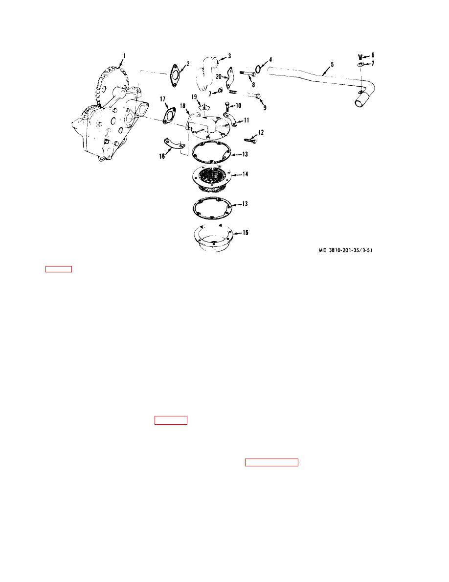
KEY to fig. 3-51:
1
Oil pump
6
Bolt
11
Lock
16
Locking plate
2
Gasket
7
Lock
12
Screw
17
Gasket
3
Elbow
8
Bolt
13
Gasket
18
Cover
4
Packing
9
Bolt
14
Screen
19
Retainer
5
Tube
10
Screw
15
Cover
20
Lock
Figure 3-51. Oil pump and screen, for engine model D333TA with screen exploded.
(4) Remove the four bolts and locks securing oil
(14) Remove nut (26) and washer (27), then pull
pump to crankcase, then remove the pump.
gear (29) from shaft (10).
(5) Remove six screws (10), lock (11), locking
(15) Remove gears (11 and 12) and shafts (10
plate (16), cover (15), and gasket (13), screen (14), and
and 35) from front body (5), then separate gears from
gasket (13) from cover (18).
shafts. Remove keys (36) from shafts.
(6) Remove two screws (12), cover (18), and
gasket (17) from oil pump (1).
Note. Do not remove bearings unless
(7) Remove bolt (8), bolt (9), lock (7), lock (20),
replacement is required.
elbow (3), and gasket (2) from oil pump (1).
(8) Remove two screws (17, fig. 3-52), locks
(16) Press bearings (37, 23, 30, and 2) out of
(16) and cover (18) from pump body (22).
bodys (5 and 22) as required, then remove pins (31 and
(9) Remove spring (19) and plunger (20) of
34) from body (5).
bypass valve from rear body (22).
b. Cleaning, Inspection, and Repair.
Clean,
(10) Remove bolt (7), tube (8), lock (6) and
inspect, and repair in a manner similar to that described
adapter (9) from front body (5).
in paragraph 3-46e above.
(11) Remove bolts (15 and 21), locks (14), and
c. Reassembly and Installation. Reassemble and
rear body (22) from front body (5).
install by reversing the procedures in steps (1) through
(12) Pull gears (24 and 38) from shafts (10 and
(16) of a above.
35), then remove spacer (25).
(13) Pull gear (1 ) from shaft (8) and remove
dowel (4).
3-62


