TM 5-3810-206-35
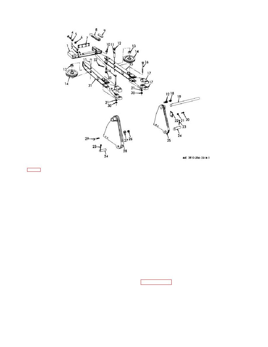
KEY to fig. 4-1:
1
Spreader bar
10
Nut
18
Reducer
26
Nut (4 rqr)
2
Keeper plate (2 rqr)
11
Sheave pin (2 rqr)
19
Shaft
27
Lockwasher (4 rqr)
3
Capscrew (4 rqr)
12
Fitting (2 rqr)
20
Capscrew (2 rqr)
28
Adapter, L.H.
4
Bolt (8 rqr)
13
Bushing (2 rqr)
21
Lockwasher (2 rqr)
29
Bolt (4 rqr)
5
Lockwasher (8 rqr)
14
Sheave (2 rqr)
22
Keeper plate
30
Nut (4 rqr)
6
Nut (8 rqr)
15
Yoke, R.H.
23
Cotterpin (4 rqr)
31
Yoke, L.H.
7
Gusset plate
16
Bolt (8 rqr)
24
Pin (2 rqr)
32
Cotterpin
8
Rope socket
17
Bearing block (4 rqr)
25
Adapter, R.H.
33
Bolt, special
9
Rope wedge
Figure 4-1. Gantry sheave yoke and adapters, exploded view.
Check all mounting hardware for burs, stripped threads,
(3) Repair by straightening bends, welding
elongated holes, or other defect.
cracks, or replacing defective parts or mounting
hardware.
Section II. CAB
4-4.
General
4-5.
Cab and Operator Seat
The cab over revolving frame completely encloses
a. Removal and Installation.
Instructions on
machinery and operators controls. It consists of a rigid
removing or installing cab as an assembly is covered in
steel framework, panels, doors, and windows. The
sheet metal sections, bolted to the framework can be
b. Component Removal or Installation.
removed individually, or the cab can be removed as an
(1) Remove or install door or window glass (TM
assembly.
5-3810-206-12).
4-2


