TM 5-3810-206-35
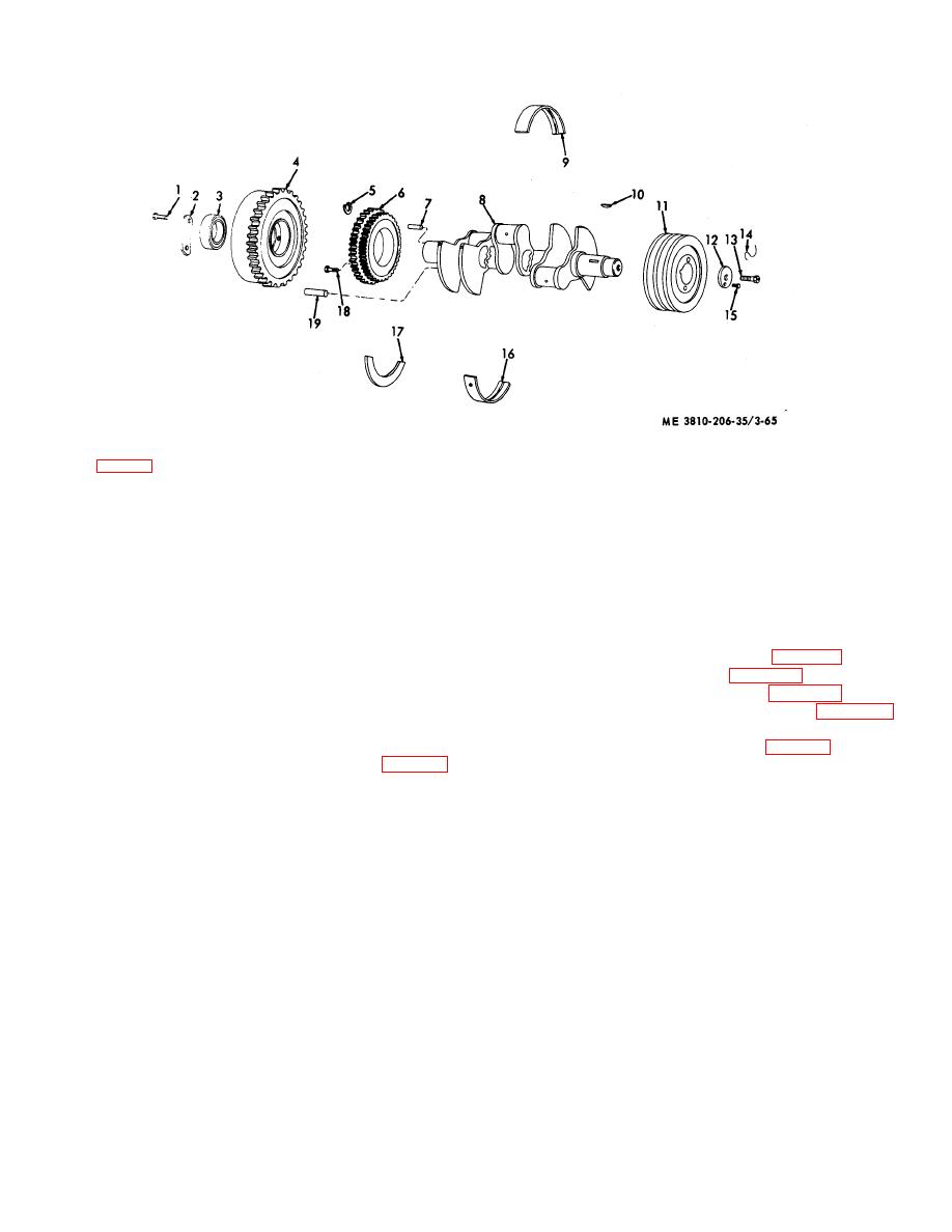
KEY to fig. 3-65:
1
Capscrew (6 rqr)
6
Crankshaft gear
11
Crankshaft pulley
16
Lower main bearing
2
Lock (3 rqr)
7
Dowel pin
12
Retainer washer
(7 rqr)
3
Bearing
8
Crankshaft
13
Capscrew (2 rqr)
17
Thrustwasher
4
Flywheel
9
Upper main bearing
14
Lockwire
18
Capscrew (4 rqr)
5
Retainer ring (2 rqr)
(7 rqr)
15
Capscrew
19
Flywheel dowel pin
10
Key
(2 rqr)
Figure 3-65. Crankshaft and flywheel for engine model 687C-18-ES, exploded view.
(6) Remove capnuts ( ) from the seven main
1
a. Removal and Installation.
bearing caps (7), then remove bearing caps.
(1) Remove flywheel housing (para 3-41).
(7) Use a suitable sling and lifting device to
(2) Remove front cover (para 3-31).
remove crankshaft (14) from crankcase.
(3) Remove oil pan and plate (para 3-44).
(8) Install crankshaft by reversing procedures in
(4) Remove connecting rod caps (para 3-58)
steps (1) through (7) above.
and push pistons up into cylinders and out of way.
b. Disassembly and Re assembly.
(5) Remove 14 cotterpins (1, fig. 3-66), nuts (2)
(1) Remove upper main bearings (9, fig. 3-65)
and seven main bearing caps (3, 4, and 5) from studs on
from crankcase. Tag each one so that it can be
crankcase (6). Remove the rear lower flanged bearing
reinstalled in its same position.
half (7) and six lower bearing halves (8) from bearing
(2) Remove thrustwasher (17) from crankshaft
caps.
(8).
(3) Reassemble by reversing procedures in
Note.
If bearings are not to be
steps (1) and (2) above.
replaced, keep halves together with
c. Cleaning, Inspection, and Repair.
their cap, marked for reinstallation in
(1) Clean all parts and dry thoroughly before
the same place from which removed.
inspection or reassembly.
(2) Inspect main bearings and crankshaft
(6) Remove crankshaft gear (9) and key (10)
journals for wear or other damage. Main bearing oil
from crankshaft (11).
clearance must not exceed 0.008 inch.
(7) Use suitable sling and lifting device and
(3) Inspect mounting hardware for burs or other
remove crankshaft (11) from crankcase (6).
defect. Replace defective mounting hardware.
(8) Remove seven upper bearing halves (12)
from crankcase (6).
(9) Remove studs (13 and 14) as required.
3-61. Crankshaft and Main Bearings (Engine Model
(10) Install main bearings and crankshaft by
D333TA)
3-78


