TM 5-3810-206-35
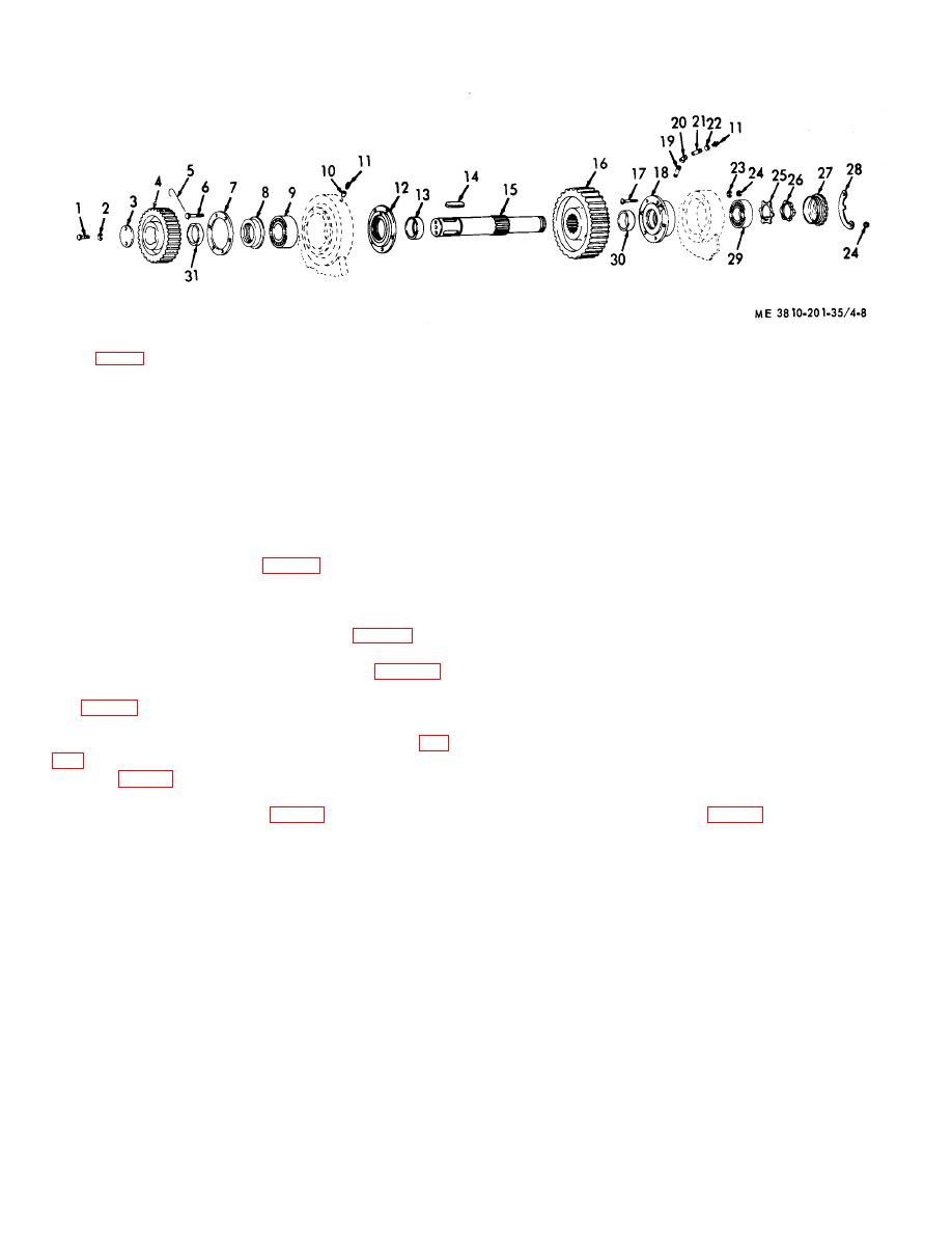
KEY to fig. 4-8:
1
Capscrews (2 rqr)
9
Bearing
17
Capscrews (5 rqr)
25
Key washer
2
Lockwasher (2 rqr)
10
Pipe hushing
18
Housing
26
Nut
3
Collar
11
Fittings (2 rqr)
19
Pipe nipple
27
Bearing retainer
4
Spur gear
12
Bearing retainer
20
Elbow
28
Lock plate
5
Wire
13
Spacer
21
Pipe nipple
29
Bearing
6
Screw (6 rqr)
14
Key (2 rqr)
22
Pipe coupling (2 rqr)
30
Spacer
7
Retainer plate
15
Shaft
23
Lockwasher (5 rqr)
31
Spacer
8
Bearing retainer
16
Spur gear
24
Nut (5 rqr)
Figure 4-8. Intermediate hoist shaft, exploded view.
(3) Support gear (11, fig. 4-6) on right hand end
then remove bearing (29) from housing
of shaft.
(18).
(4) Remove nuts (8) and lockwashers. Remove
c. Cleaning, Inspection, and Repair.
locking plate (9) and bearing retainer (10).
(1) Clean all parts and dry thoroughly.
(5) Remove bearing locknut (26, fig. 4-8) and
(2) Inspect shaft for burred splines or excessive
lockwashers (25) from end of shaft (15).
wear; bearings for excessive wear or other damage;
(6) Remove two capscrews (14, fig. 4-5),
gears for broken, cracked or chipped teeth, and spacers,
lockwashers (13), and collar (12) from left end of shaft
seals, or retainers, for any damage or defect. Inspect
(15, fig. 4-8).
mounting hardware for burs, elongated holes, or other
(7) Remove bearing retainer from housing.
defect.
(8) Remove shaft (15) and outside gear (11, fig.
(3) Repair by straightening bends, welding
cracks, or replacement of defective parts or mounting
gear (11, fig. 4-6) from revolving frame.
hardware.
b. Disassembly.
d. Reassembly.
(1) Remove gear (4, fig. 4-8) from left end of
(1) Install nipple (19, fig. 4-8) and elbow (20) on
shaft (15).
bearing housing (18).
(2) Cut wire (5) and remove capscrews (6),
(2) Install nipple (21), coupling (22) and fitting
spacer (30), retainer plate (7), and bearing retainer (8)
(11) on elbow (20).
from shaft (15).
(3) Install spaces (13) and (30), and bearing
(3) Press bearing (9) off shaft (15).
housing (18) on shaft (15), then press bearing (9) on
(4) Remove bearing retainer (12) and spacers
shaft (15).
(13) and (30) from shaft (15).
(4) Position bearing retainer (8), retainer plate
(5) Remove fitting (11), coupling (22), and
(7), and spacer (30) on shaft (15) and secure to bearing
nipple (21) from elbow (20).
enclosure with capscrews (6), and wire (5).
(6) Remove elbow (20) from nipple (19) then
(5) Install keys (14) and gear (4) on keyed end
remove nipple from bearing housing (18).
of shaft (15).
(7) Remove bearing housing (18) from frame,
e. Installation.
(1) Raise shaft to sidestand and drive it through.
4-11


