TM 5-3810-206-35
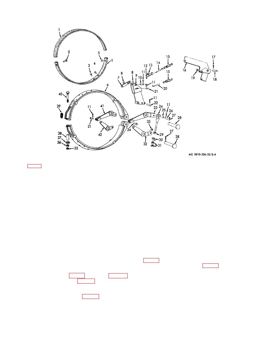
KEY to fig. 5-4:
1
Lining (2 rqr)
15
Tension spring
29
Nu t (2 rqr)
2
Rivet (6 rqr)
(2 rqr)
30
Trunnion (2 rqr)
3
Rivet (22 rqr)
16
Bracket
31
Nut (2 rqr)
4
Rivet (6 rqr)
17
Cotterpin (8 rqr)
32
Lever (2 rqr)
5
Rivet (8 rqr)
18
Pin (2 rqr)
33
Bearing (2 rqr)
6
Brake band (2 rqr)
19
Washer (12 rqr)
34
Pin (8 rqr)
7
Link (4 rqr)
20
Link (2 rqr)
35
Nut (2 rqr)
8
Washer (2 rqr)
21
Pin (2 rqr)
36
Nut (2 rqr)
9
Lever (2 rqr)
22
Pin (2 rqr)
37
Washer (2 rqr)
10
Pin (2 rqr)
23
Lever (2 rqr)
38
Spacer (2 rqr)
11
Cotterpin (2 rqr)
24
Clevis (2 rqr)
39
Spring (2 rqr)
12
Link (2 rqr)
25
Bearing (4 rqr)
40
Bolt (2 rqr)
13
Nut (2 rqr)
26
Pin (2 rqr)
41
Lever (2 rqr)
14
Bolt, Hook
27
Cotterpin (4 rqr)
42
Lever (2 rqr)
(2 rqr)
28
Pin (4 rqr)
Figure 5-4. Propelling brake and levers, exploded view.
(2) Insure that keys (18 and 19) are in shaft (17)
clutch on horizontal propelling shaft, then install pin (8,
then place left and right hand levers (5 and 2), collar set
(6), and lever (27) on shaft (17).
(3) Secure nuts (3, fig. 5-2) on lever (2), and
e. Installation.
setscrew (10) on collar (7).
(1) Place shaft (5, fig. 5-2) in position (para 5-4c
(4) above) and install pin (8, fig. 5-3) which connects
5-6.
Propelling Brakes and Brake Levers
lever (7) to clevis (10).
a. Removal and Installation. Remove or install
(2) Install shifter yoke (6, fig. 5-2) around jaw
propelling brakes and brake levers (TM 5-3810-206-12).
5-4


