TM 5-3810-206-35
Section II. STEERING AND PROPELLING MECHANISM
(5) Drive shaft (1) out through side frame of
5-3.
General
crawler and remove the right-hand lever (2), links (29),
The steering and brake lever shafts and propel clutch
and left-hand lever (5).
shifters, two of each, are located in the crawler. They
(6) Drive shaft (1) back far enough and remove
are linked with the propel brakes and jaw clutches on the
collar set (6).
horizontal propelling shaft. The two steering and brake
(7) Work shaft (17) out through bottom of
lever shafts are identical. Either can be removed or
crawler mounting and remove lever (15) and cam.
installed by the procedure described below. The two
(8) Separate bolt (26), clevis (10), spacer (22),
propelling brakes are accessible from underneath the
block (23), washer (12), spring (24), nuts (25 and 4) from
crawler.
right-hand lever.
(9) If necessary, remove nuts (4), lockwasher
(3), and capscrews (16) from lever (15).
5-4.
Steering and Brake Lever Shaft
(10) Repeat steps (8) and (9) above for left-hand
a. Removal and Disassembly.
lever.
(1) Release propel brake lock and place propel
(11) Remove bearing (13), roller (12), and
brake lever in neutral position, then place steering wheel
washer (14) from lever (15).
in position to disengage both clutches and shutoff engine
(12) Remove keys (35) from shaft (1), and keys
(TM 5-3810-206-12).
(18, 19, and 20) from shaft (17).
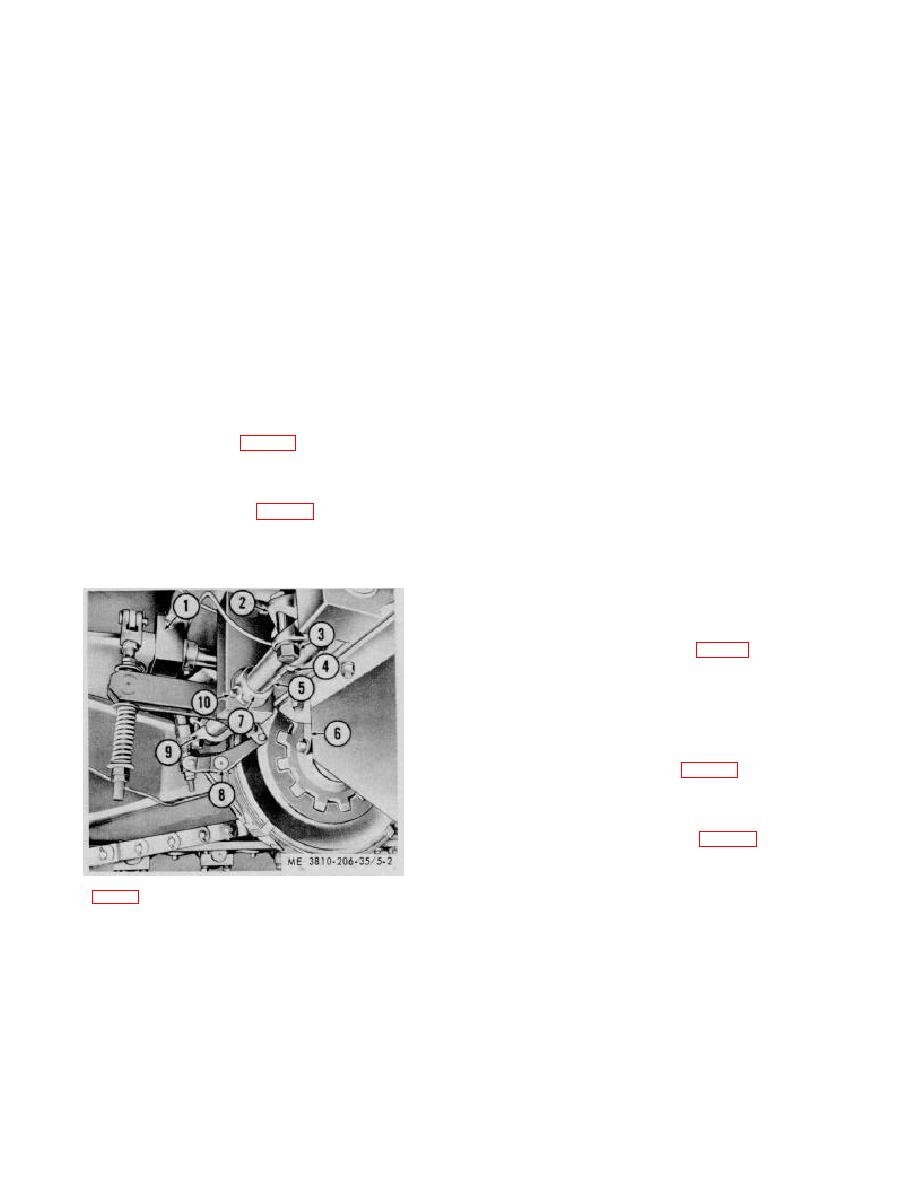
(2) Loosen nut (3, fig. 5-2) from bolts on cam
b. Cleaning, Inspection, and Repair.
lever (2) and setscrew (10) on collar (7) and drive shaft
(1) Clean all parts and dry thoroughly.
(5) in and then back to make keys (4) accessible, then
(2) Inspect levers, links, clevis, spring, guide
remove keys (4) from shaft (15).
blocks, shifter yokes, and collar sets for cracks, breaks,
(3) Remove pin (8, fig. 5-3) and disconnect
excessive wear (elongation), or other damage. Inspect
clevis from lever on propel clutch shifter shaft.
pins and shafts for straightness, wear, or roughness.
(4) Loosen setscrew (36) on collar set (6) and
Inspect bearings for scoring or wear.
loosen nuts (4) on three levers (7, 15, and 27).
(3) Repair by welding cracks and breaks, or
straightening bends. Replace all damaged parts that
cannot be repaired.
Replace defective mounting
hardware.
c. Reassembly and Installation.
(1) Install washer (14, fig. 5-3), roller (12), and
bearing (13) on cam lever (15).
(2) Install capscrews (16 and 34), lockwasher
(3), and nut (4) in levers (15, 2, and 5).
(3) Assemble bolt (26), clevis (10), spacer (22),
spring block (23), washer (21), spring (24), washer (21)
and nuts (4 and 25) on lever (27).
(4) Raise shaft (5, fig. 5-2) into position on
under side of crawler mounting, install key (4), in shaft
(5), then install collar (7) and lever (2) on shaft (5).
(5) Change position of shaft (5) as required,
then install right hand lever (2, fig. 5-3), links (29), and
left hand lever ((5) on shaft (1).
(6) Position keys (35), and lever (7) on shaft (1)
and clevis (10).
KEY to fig. 5-2:
(7) Position lever (30) on link (29) of propelling
brake linkage then install pin (8).
1
Bracket
6
Yoke shifter
2
Lever
7
Collar
3
Nut
8
Pin (2 rqr)
4
Key
9
Lever
5
Shaft
10
Setscrew (2 rqr)
Figure 5-2. Steering and brake level shaft, removal and
installation.
5-2


