TM 5-3810-206-35
CHAPTER 5
CRAWLER REPAIR INSTRUCTIONS
Section I. ROLLER (TURNTABLE) CIRCLE
(2) Lift turntable roller circle from roller path of
5-1.
General
crawler (fig. 5-1).
The roller (turntable) circle is supported by roller path on
b. Disassembly and Reassembly.
crawler. The inner and outer segments position rollers
(1) Remove or install rollers from inner and
uniformly around the roller path.
Load is evenly
outer turntable roller circle segments (TM 5-3810-206-
transmitted from upper rotating machinery to crawler
12).
frame as the revolving frame swings around the crawler.
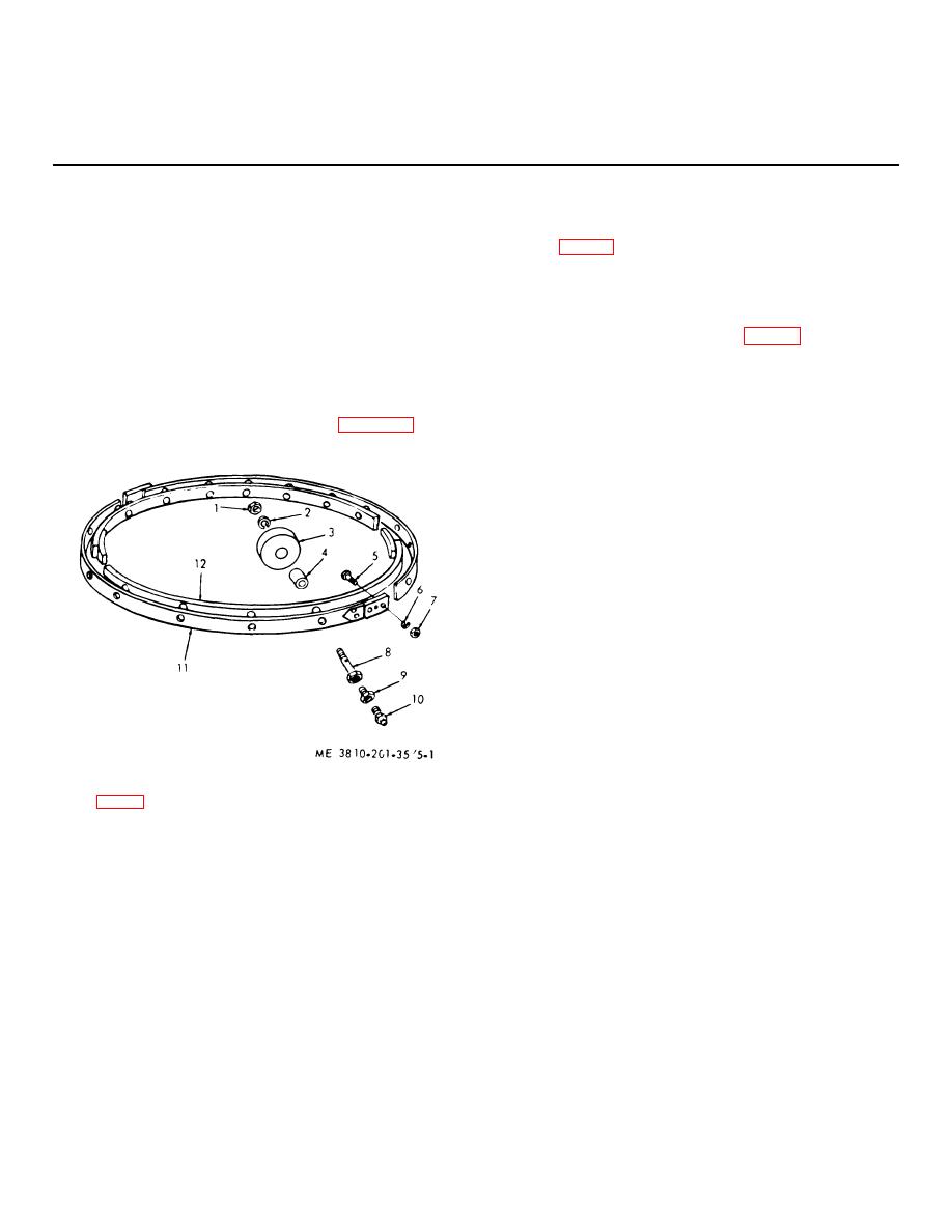
(2) Remove eight nuts (7, fig. 5-1), lockwashers
(6), and capscrews (5) then separate the two outer
turntable roller segments (11).
5-2.
Roller (Turntable) Circle
(3) Remove eight nuts, lockwashers, and
a. Removal and Installation.
capscrews, then separate two inner turntable roller
(1) Remove the revolving frame (para 2-10).
segments.
(4) Reassemble turntable (circle) roller by
reversing the procedures in steps (1) through (3) above.
c. Cleaning, Inspection, and Repair.
(1) Clean all parts and dry thoroughly.
(2) Inspect the four segments for cracks,
breaks, or excessive wear at roller holes for fluid
passage bolts. Inspect rollers for excessive external
wear (flat spots), or bushing wear. Inspect fluid passage
bolts for damaged external or internal threads, or
excessive body wear. Assure that lubrication fittings will
admit grease.
(3) Repair roller segments by welding cracks or
breaks. Replace defective segments. Repair roller
circle by replacing defective rollers. When individual
rollers are replaced, machine outer surface of new
rollers until all 24 rollers do not vary more than 0.005
inch. Replace defective fluid passage bolts, lubrication
fittings, or mounting hardware.
KEY to fig. 5-1:
1
Nut (24 rqr)
7
Nut (16 rqr)
2
Lockwasher (24 rqr)
8
Fluid passage bolt (24 rqr)
3
Roller (24 rqr)
9
Bushing (24 rqr)
4
Shaft (24 rqr)
10
Fitting (24 rqr)
5
Capscrew (16 rqr)
11
Outer segment (2 rqr)
6
Lockwasher (8 rqr)
12
Inner segment (2 rqr)
Figure 5-1. Roller circle, exploded view.
5-1


