TM 5-3810-206-35
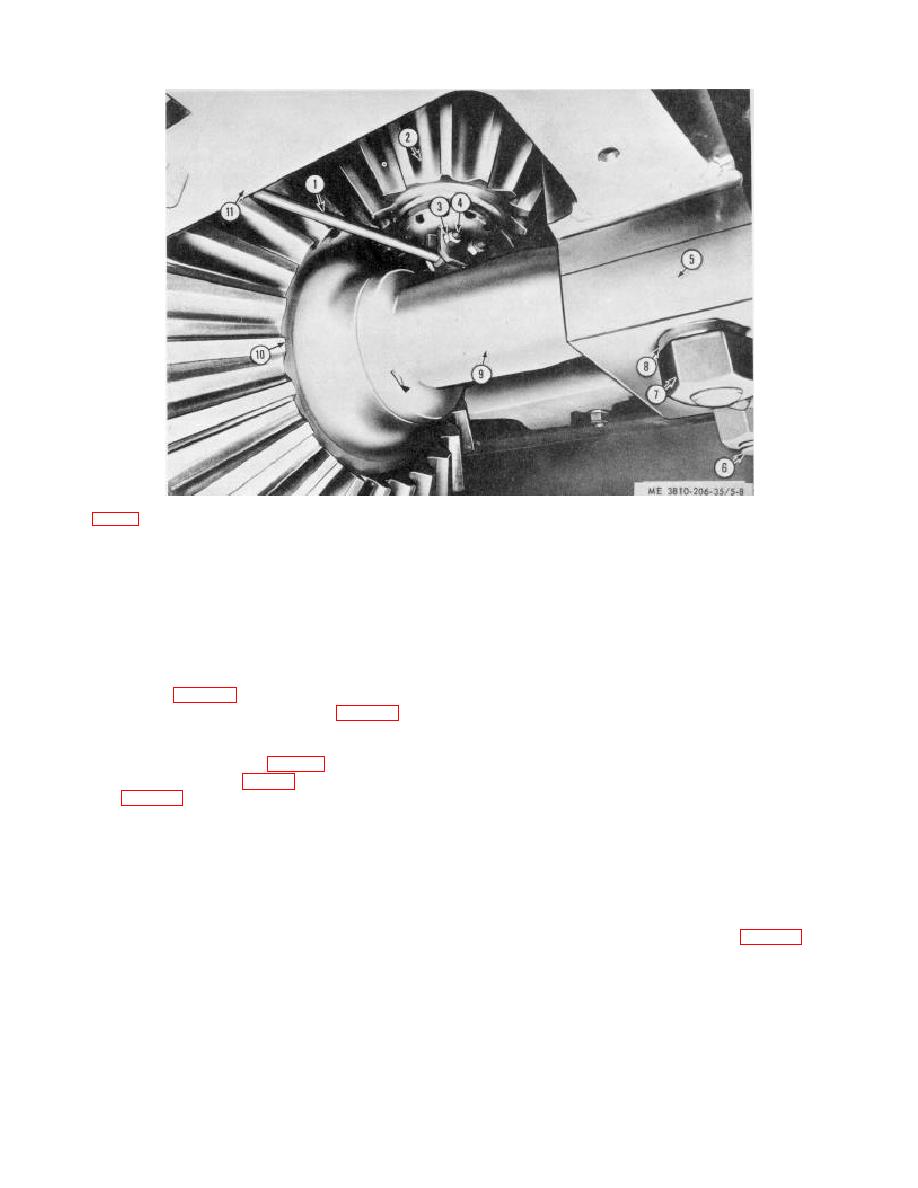
KEY to fig. 5-8:
1 Lubrication line
4 Bolt (2 rqr)
7 Nut (8 rqr)
10 Propelling gear
2 Bevel gear
5 Bearing cap
8 Lockwasher (8 rqr)
11 Propelling gear case
3 Nut (2 rqr)
6 Bolt (8 rqr)
9 Propelling shaft
Figure 5-8. Horizontal propelling shaft, installed view.
washers (24), capscrews (27), oil pan (25), and gaskets
capscrews (10), and two halves of collar (9) from
(22, 26, and 30) from carbody (54).
shaft (8).
(8) Disconnect yokes of propel clutch shifter
(16) Remove two sleeve bearings (1) from each
from jaw clutches (para 5-5).
brakedrum (5).
(9) Support weight of shaft (9, fig. 5-8) and
b. Cleaning, Inspection, and Repair.
remove nuts (7), lockwashers (8), bearing cap (5), and
(1) Clean all parts and dry thoroughly.
bolts (6).
(2) Inspect brakedrums, jaw clutches, and
(10) Remove bolt (31, fig. 5-6), bearing caps
adjusting collar for cracks, breaks, or other damage.
(21), bearings (4, 7, and 13, fig. 5-9), and shims (33, 34,
Inspect gear, sprockets, and bearings for damage or
and 51, fig. 5-6).
Mark bearings and shims for
excessive wear. Inspect mounting hardware for burred
reassembly in proper position.
threads or other damage. Inspect gaskets for tears or
(11) Pull brakedrum (5) off each end of shaft (8).
deterioration. Inspect shaft for straightness, out-of-
(12) Pull sprocket wheels (2) off brakedrums (5).
round, worn bearing surfaces, or other damage.
Remove key (3) from each brakedrum (5).
(3) Repair minor cracks or breaks in
(13) Pull jaw clutch half (6) from each en d of
brakedrums, jaw clutches or collar by welding. Replace
shaft (8).
defective components, gaskets, or mounting hardware.
(14) Press bevel gear (11) off shaft (8) and
c. Reassembly and Installation.
remove keys (14).
(1) Install two bearings (1, fig. 5-9) in each
(15) Remove two nuts (16), lockplate (17),
brakedrum (5).
5-10


