TM 5-3810-206-35
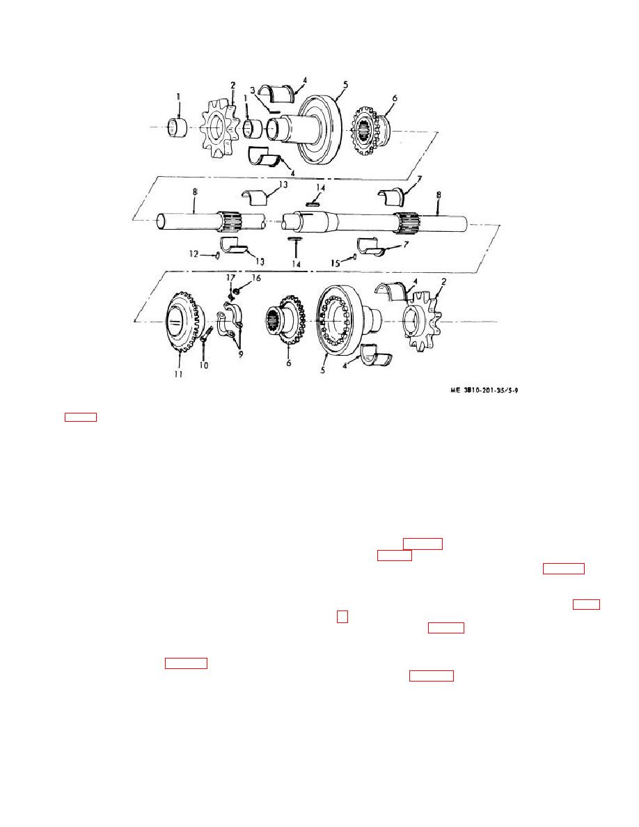
KEY to fig. 5-9:
1
Sleeve bearing (4 rqr)
7
Flanged hearing half
12
Pin (4 rqr)
2
Sprocket wheel (2 rqr)
(2 rqr)
13
Sleeve bearing half (2 rqr)
3
Key (4 rqr)
8
Shaft
14
Key (2 rqr)
4
Sleeve bearing halves
9
Adjus ting collar
15
Pin (4 rqr)
(4 rqr)
10
Capscrew (2 rqr)
16
Nut (2 rqr)
5
Brakedrum (2 rqr)
11
Bevel gear
17
Lockplate (2 rqr)
6
Jaw clutch half (2 rqr)
Figure 5-9. Horizontal propelling shaft, exploded view.
(2) Reassemble halves of adjus ting collar (9) on
(4, 7, and 13, fig. 5-9) on shaft (8). Secure with bearing
shaft (8) and secure with capscrews (10), lockplate (17),
caps (5, fig. 5-8), bolts (6), lockwashers (8), and nuts (7).
and nuts (16).
(9) Install shims (33, 34, and 51, fig. 5-6) as
(3) Install two keys (14) on shaft (8) and press
marked for reassembly, then install bearing caps (21)
bevel gear (11) into position.
and bolts (31).
(4) Slip a jaw clutch (6) on each end of shaft (8).
(10) Adjust position of propelling gear (10, fig. 5-
(5) Install two keys (3) on each brakedrum (5)
and press a sprocket (2) on each brakedrum (5).
adjusting collar (9, fig. 5-9) and moving it in or out until
(6) Install brakedrum (5) on each end of shaft
gears are properly aligned. Secure adjusting collar in
(8).
position by tightening two nuts (16) on bolts (10).
(7) Raise shaft (9, fig. 5-8) as assembled, into
(11) Connect shifter yokes of propel clutch shifter
position from underneath the crawler.
to jaw clutches (para 5-5).
(8) Support weight of shaft and install bearings
(12) Install propel chains (TM 5-3810-206-12).
5-11


