TM 5-3810-206-35
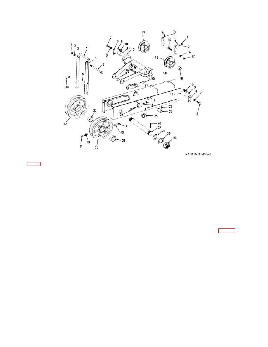
KEY to fig. 6-2:
1
Nut (5 rqr)
9
Fitting (6 rqr)
19
Boom
28
Flatwasher (2 rqr)
2
Lockwasher
10
Bushing (4 rqr)
20
Wedge
29
Flatwasher (2 rqr)
(17 rqr)
11
Pin (2 rqr)
21
Socket
30
Cotterpin (2 rqr)
3
Guard, R.H.
12
Bar
22
Cotterpins
31
Sleeve (2 rqr)
4
Spacer
13
Sheave (2 rqr)
(2 rqr)
32
Sheave (2 rqr)
5
Guard, L.H.
14
Strap (2 rqr)
23
Pin
33
Bearing, sleeve (2 rqr)
6
Bolt
15
Bolt (2 rqr)
24
Bolt (8 rqr)
34
Capscrew (4 rqr)
7
Capscrew (4 rqr)
16
Lockwasher (2 rqr)
25
Blocks (4 rqr)
35
Capscrew (4 rqr)
8
Keeper plate
17
Nut (2 rqr)
26
Cotterpin (2 rqr)
36
Clamp, bridle shaft
(2 rqr)
18
Bushing (4 rqr)
27
Pin, boom point
(2 rqr)
Figure 6-2. Bridle bar and boom point sheaves, exploded view.
(3) Repair by welding cracks and breaks, and
(2)
Remove two nuts (25, fig. 6-3) and rod
replacing defective components or damaged mounting
end (24) from shaft (5).
hardware.
(3) Remove shaft (5) and sprocket (2) from
c. Reassembly and Installation. Reassemble and
yoke (6).
install bridle bar and boom point sheaves by reversing
(4) Press sleeve bearing (1) out of sprocket (2).
procedures in a above.
(5) Remove crowd and retract gear guard (TM
5-3810-206-12).
(6) Remove two nuts (10), lockwashers (12),
6-4.
Crowd and Retract Mechanism
capscrew (14), and collar (13) from shaft (17).
a. Removal and Disassembly.
(7) Use a gear puller and remove shaft (17)
(1) Remove shovel front end attachment (TM 5-
3810-206-12).
6-3


