TM 5-3810-207-20/TO 36C23-3-37-12
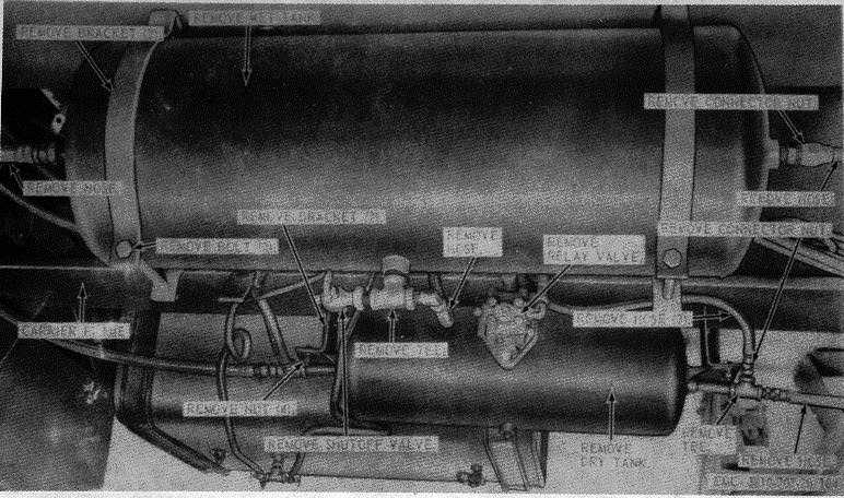
Figure 184. Wet and dry air tank, removal and installation.
(2) Inspect the air manifold for proper
operation. Replace a defective air
manifold.
(3) Inspect
all
fittings
and
mounting
hardware for stripped or damaged
threads. Replace as necessary.
(4) Inspect all hoses for cracks, breaks, and
deterioration. Replace as necessary.
c.
Installation. Install the rear air manifold as
illustrated on figure 185.
303. Air Emergency and Service Shutoff Valves
a.
Removal. Remove the air emergency and
service shutoff valves as instructed on figure 185.
b.
Cleaning and Inspection.
(1) Clean all parts with an approved
cleaning solvent.
(2) Inspect the air emergency and service
valves for proper operation. Replace
defective valves as necessary.
(3) Inspect
all
nipples
and
mounting
hardware for stripped or damaged
threads. Replace all defective parts as
necessary.
(4) Inspect the coupling for breaks and
other damage. Replace coupling and
defective parts.
c.
Installation. Install the air emergency and
service shutoff valves as illustrated on figure 185.
304. Front Brakeshoes
a.
Brakeshoes Removal.
(1) Remove the wheel and drum from
brakeshoe assembly (par. 283).
(2) Remove
the
front
brakeshoes
as
instructed on figure 186.
b.
Slack Adjuster Removal. Remove the slack
adjuster as instructed on figure 187.
c.
Cleaning and Inspection.
(1) Clean all parts with an approved
cleaning solvent except the brake lining,
and dry thoroughly.
(2) Inspect the brake lining for excessive
wear and glazing. Remove glazing by
brushing with a wire brush.
238


