TM 5-3810-207-20/TO 36C23-3-37-12
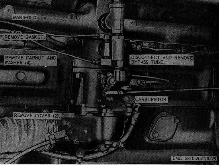
Figure 29. Valve cover assembly, removal and installation.
93. Engine Governor Assembly
a.
Removal. Remove the crane engine governor
assembly as instructed on figure 31.
b.
Cleaning and Inspection.
(1)
Clean the governor assembly with an
approved
cleaning
solvent
and
dry
thoroughly.
(2)
Inspect the governor assembly for cracks,
breaks, proper operation, and other
damage. Replace defective governor
assembly.
c.
Installation. Install the governor assembly as
illustrated on figure 31.
d.
Adjustment. Adjust governor assembly (par.
94).
94. Governor Adjustment
a.
Engine Speed Governor Adjustment.
(1)
Start the engine and allow it to operate
until
it
reaches
normal
operating
temperature (TM 5-3810-207-10).
(2)
Loosen locknut on governor adjusting
screw (fig. 32) and back out on the
adjusting screw several turns to make
sure it does not affect the engine speed.
(3)
Use a tachometer and check the engine
speed with the engine pulling its rated
load. If the desired engine speed cannot
be obtained, increase or decrease the
tension
of
the
governor
spring
by
loosening the adjusting nut and lowering
or raising the adjusting eyebolt to obtain
desired speed range.
(4)
Secure the adjusting eyebolt in place with
the locknut.
(5)
If the governor surges at no-load speed
after
spring
tension
is
adjusted,
55