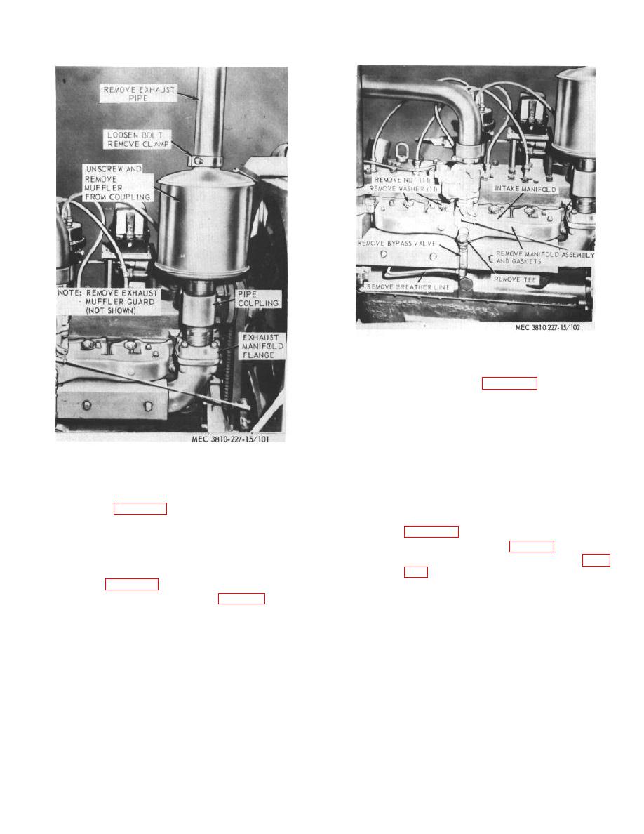
Figure 102. Manifolds, removal and installation.
as instructed on figure 102.
b. Cleaning and Inspection.
(1) Clean the manifolds with a wire brush.
(2) Inspect the manifolds for cracks, breaks,
and other damage. Replace defective
Figure 101. Exhaust pipe and muffler, removal and
manifolds,
gaskets,
and
mounting
installation.
hardware.
c. Installation.
as illustrated on figure 101.
(1) Install the manifolds as illustrated on
176. Intake and Exhaust Manifolds
(2) Install the carburetor (para. 93).
a. Removal.
(2) Remove the carburetor (para. 93).
Section XV. CARRIER ENGINE CLUTCH ASSEMBLY
accomplished by turning the threaded adjusting ring to
177. General
compensate for facing wear. The clutch is operated by
mechanical linkage from the operator's cab. This
The carrier engine clutch is a double-plate, dry disc,
mechanical linkage must be kept in adjustment.
adjustable, pull type, multiple lever design. No special
tools are required for maintenance. Adjustment is
AGO 6819A
126


