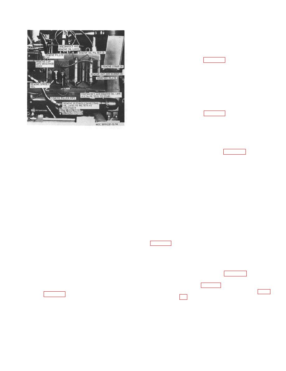
(3) Start engine and check filters for leaks.
165. Crankcase Filler and Breather
breather as instructed on figure 94.
b. Cleaning and Inspection.
(1) Clean all parts with an approved
cleaning solvent.
(2) Inspect all parts for breaks, cracks, and
other damage.
Replace all defective
parts.
breather as illustrated on figure 94.
166. Oil Pressure Relief Valve
Figure 94. Crane engine, oil filters, crankcase filler,
The oil pressure relief valve, located on the right
and breather, removal and installation.
side of the engine block, is the same as the relief valve
on the carrier engine and is removed, repaired, adjusted
(2) Fill crankcase to proper operating level
and installed in the same manner (para. 162).
(LO 5-3810-227-15).
Section XIII. CARRIER ENGINE INTAKE AND EXHAUST SYSTEM
167. General
(1) Clean all parts in an approved cleaning
solvent with a wire brush.
The intake and exhaust system consists of the
(2) Inspect muffler for cracks, holes, leaks,
and other damage.
exhaust manifold expels burned exhaust gas from the
(3) Inspect the tailpipe for bends, cracks, rust,
cylinders, through the exhaust pipe and muffler, to the
and other damage.
atmosphere. The intake manifold delivers the air and
(4) Inspect all clamps and mounting
fuel mixture to each cylinder. The six intake and six
hardware. Replace all defective muffler
exhaust valves are located in the cylinder heads and are
parts as necessary.
actuated by the camshaft through the tappets, push
rods, and rocker arms. Adjusting screws in the rocker
c. Installation. Install the muffler as illustrated on
arms provide the means of adjusting the valve
clearance. The stem of each valve slides within a guide
pressed into the cylinder heads. The intake valves
control the admission of the fuel-air mixture to the
169. Intake and Exhaust Manifold
cylinders, while the exhaust valves permit the expulsion
of gases from the cylinders.
a. Removal.
(1) Remove the muffler (para. 168).
168. Muffler
(2) Remove the carburetor from the intake
manifold (para. 86).
a. Removal.
Remove the carrier muffler as
(3) Remove the fuel lines and fittings (para.
instructed on figure 95.
b. Cleaning and Inspection.
AGO 6819A
122


