(2) Inspect all parts for breaks, excessive
c. Reassembly and Installation. Reassemble and
wear, and other damage.
Repair or
install the boom angle indicator in the reverse of the
replace all defective parts as necessary.
numerical sequence as illustrated on figure 125.
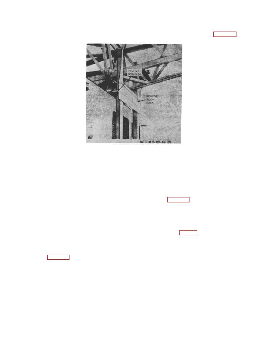
Figure 124. Boom rack, removal and installation.
Section XXII. CRANE CAB ASSEMBLY
208. General
(2) Inspect the door for bends, broken glass,
and other damage. Replace defective
The crane cab is located on the revolving frame and
operator's door or glass.
incloses the revolving frame shaft assemblies, A-frame,
c. Installation.
Install the operator's door as
engine with accessories, and all levers, pedals, and
illustrated on figure 126.
linkage controls. It is constructed of sheet-steel welded
panels and doors, has glass windows, and is fastened to
210. Door Window and Windshield Glass
the floor of the revolving frame with capscrews and
a. Removal.
(1) Insert the hook end of the rubber channel
209. Operator's Door
tool (fig. 127) in the rubber channel seal
strip at the seam and slide tool around the
a. Removal.
channel to break the seal.
(1) Open the operator's door.
(2) After seal has been broken, insert the
(2) Remove the operator's door as instructed
straight end of the rubber channel tool
in figure 126.
between the rubber channel and the glass
b. Cleaning and Inspection
and move it slowly around the rubber
channel to break the seal.
(1) Clean the operator's door with an
approved cleaning solvent.
(3) Press glass gently while breaking the seal
and glass will slide out of the panel as
AGO 6819A
146


