Blow out all passages of the cooler with
clean compressed air. Dry thoroughly.
b.
Inspection, Testing, and Repair.
(1) Inspect the oil filter base for cracks,
breaks, chips, or other damage and for
pits, burrs, or warping along mating
surfaces. Replace a defective oil filter
base assembly.
(2) Inspect the oil cooler for cracks, breaks,
dents, or other damage.
(3) Test the oil cooler as follows:
(a) Plug one of the water passages.
(b) Insert an air hose in the oil passage.
(c) Immerse the cooler in water and
apply 15 to 20 pounds of air
pressure.
(d) Watch for bubbles.
When they
appear, note the position of the
leaks. Mark the cooler for repair.
Solder the leaks with care, making
sure solder does not leak into core
passages where it would obstruct the
flow of water.
(4) Replace all gaskets each time the oil
filter base assembly and oil cooler are
removed.
417.
Carrier Engine Oil Filter Base and Oil Cooler
Assembly Installation
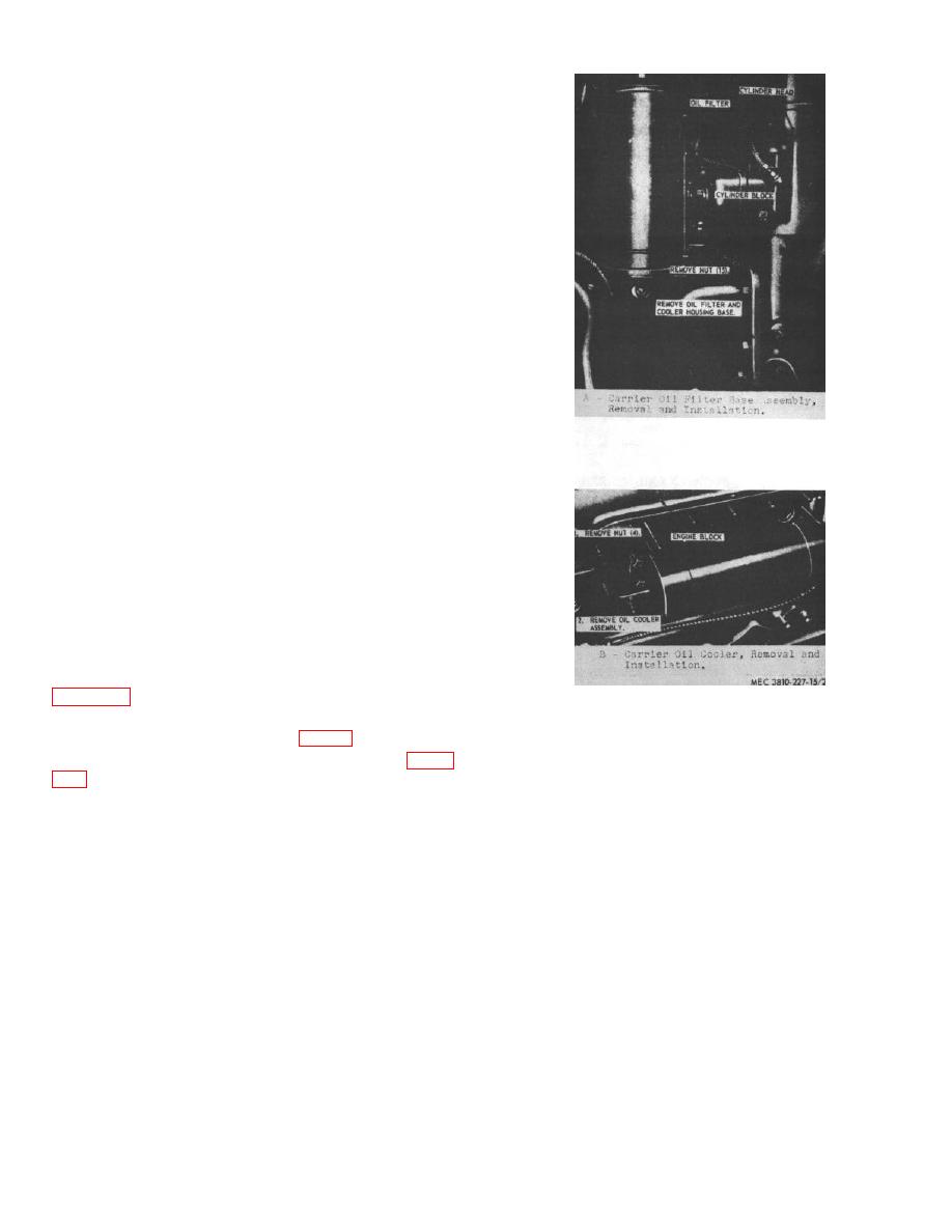
a.
Install the carrier engine oil filter base and oil
cooler assembly on the engine block as instructed on
Figure 215. Carrier engine oil filter base and oil
b.
Install the oil filters on the carrier engine oil
cooler assembly, removal and installation.
filter base and oil cooler assembly (fig. 18).
c.
Install the carrier engine assembly (para.
Section XXXIII. CARRIER ENGINE ROCKER ARM AND PUSH RODS ASSEMBLY
arms opens and closes the valves during each engine
418.
General
cycle. Drilled passages in the cylinder head provide
lubrication for the rocker arm assemblies, and ports on
An overhead valve system is used on the carrier
the side of the engine provide passages for fuel vapors
engine. Cam actuated push rods operate the rocker
and exhaust gases.
arms mounted on the engine cylinder head and
enclosed within oil-tight covers. The action of the rocker
AGO 6819A
238


