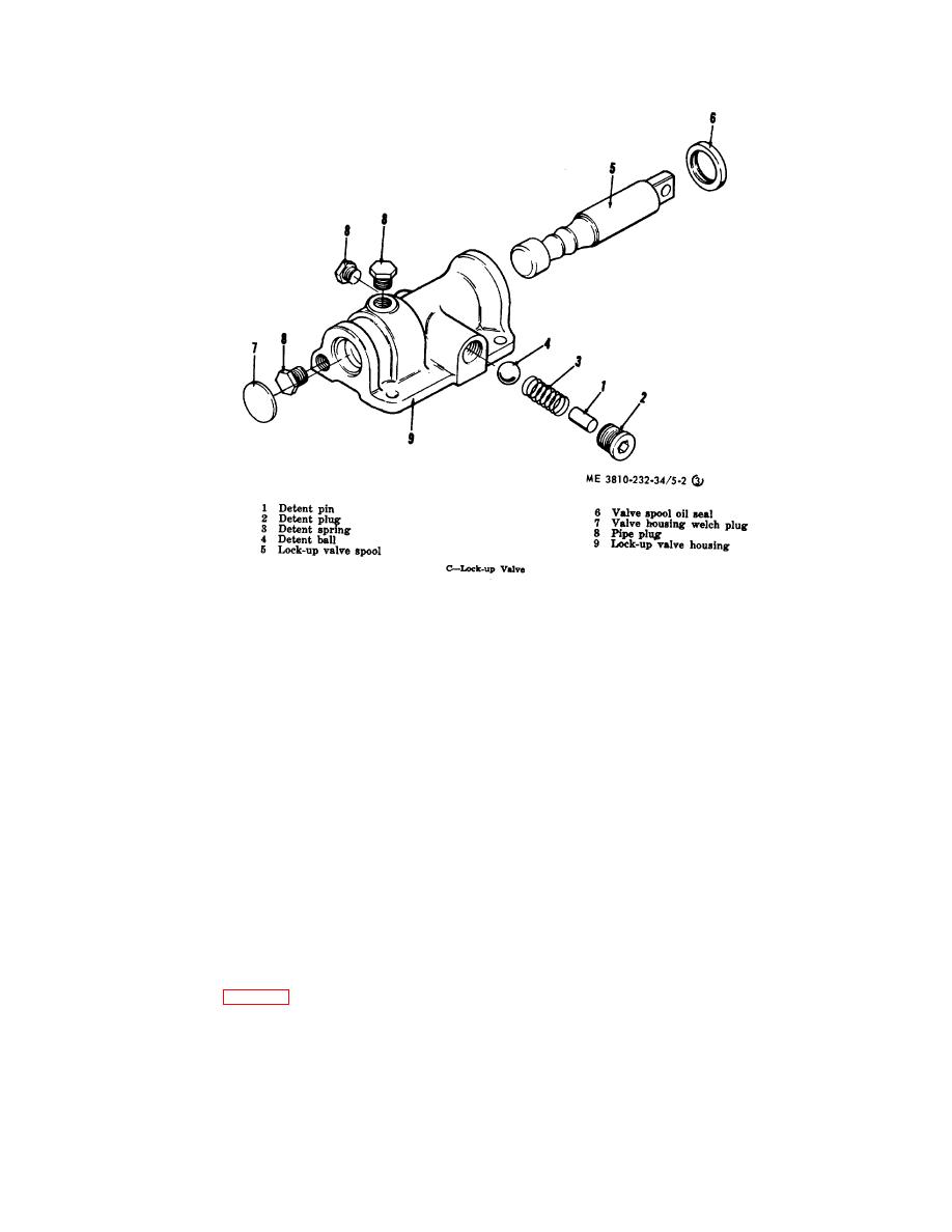
Figure 5-2. (3) --Continued.
c.
Cleaning, Inspection and Repair.
into pump driven gear. Install pump bearing retainer
washer (95) and ring (109). Install pump driven gear to
(1) Clean all parts with an approved
snap ring (83). Repeat procedure for all pump shafts
cleaning solvent anl dry thoroughly.
and gears.
(2) Inspect bearings, cages and cups for
(2) Apply a thin coat of No. 2 Permatex to
wear, chipping or nicks. Replace defective or damaged
outer diameter of oil seal (93) and press into bore of oil
bearings, both cone and cup as a set.
baffle (92). Lip of seat must be upward.
(3) Inspect gears and shafts with magnetic
inspection. Inspect all gears for wear, pitting, chipping,
nicks, cracks, or scoring. Replace defective gears.
NOTE
(4) Inspect shafts and quills to make certain
Before installing oil baffle remove
they are not sprung, bent, or splines twisted. Replace
impeller hub bolts and install new
defective shafts.
impeller to hub O-ring (87). Install oil
(5) Inspect housing, covers, and bearing
baffle on impeller and hub assembly.
caps and see that mating surfaces, bearing bores, etc.,
Use caution as not to damage oil
are free from nicks or burrs. Check all parts carefully for
seal. Install pump drive gear (52) and
evidence of cracks or conditions which would cause
snap ring (51). Install oil baffle O-ring
subsequent oil leaks or failures. Repair or replace
(118). Lubricate O-ring with type "A"
defective parts.
automatic transmission fluid. Install
(6) Replace all spring loaded oil seals, O-
stator support sealing ring (58).
rings, metal sealing rings, gaskets, and snap rings.
(3) Install impeller and oil baffle assembly
(1) Install sleeve (54). Install support self
over stator support and into converter housing. Use
locking screws (50) and tighten 70 to 86 ft-lbs torque.
caution not to damage oil baffle O-ring. Install impeller
With pump driven gear (82) in position, install pump shaft
hub bearing (86). Press roll pin
(80) and bearing assembly (81) through rear of case and
5-7


