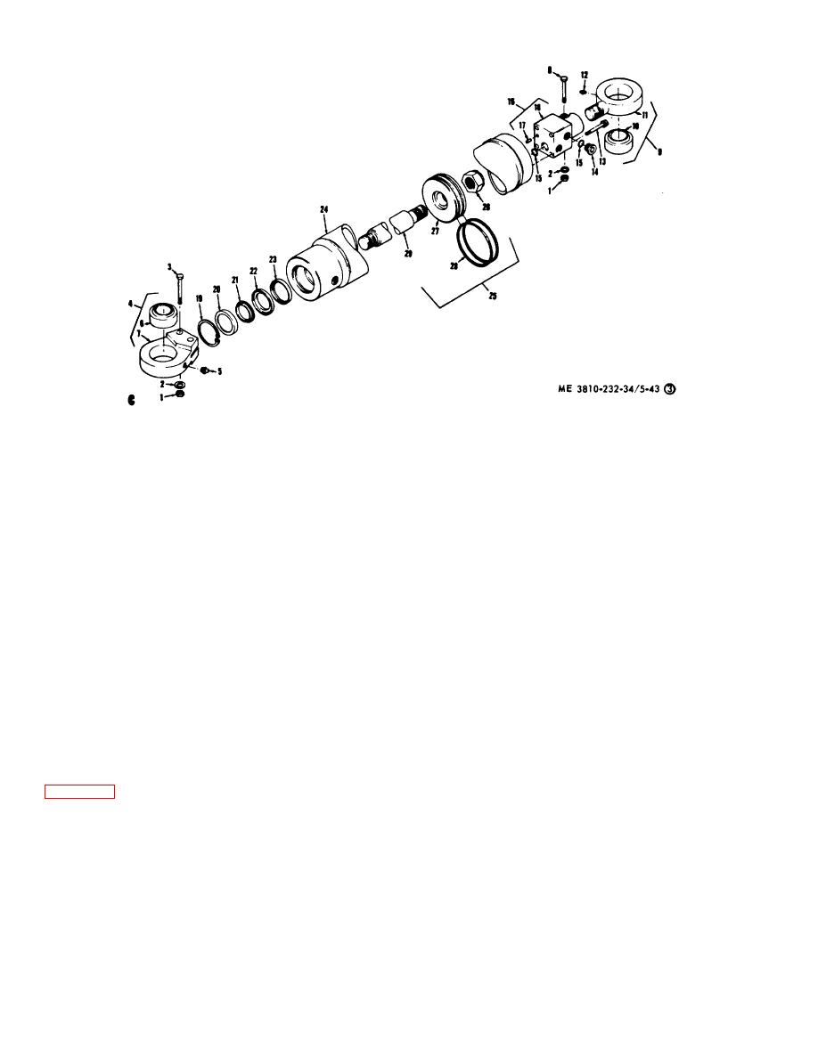
1
Nut
16
End cap assembly
2
Lockwasher
17
Roll pin
3
Bolt
18
End cap
4
Bearing assembly
19
Snap ring
5
Grease fitting
20
Scraper
6
Bearing
21
Wiper
7
Bearing housing
22
Seal retainer
8
Bolt
23
Sea;
9
Bearing assembly
24
Cylinder weldment
10
Bearing
25
Piston and rod assy
11
Bearing housing
26
Nut
12
Grease fitting
27
Piston
13
Bolt
28
Piston ring
14
Plug
29
Piston rod
15
O-ring
C -Steering cylinder
Figure 5-43. (3) - Continued.
c. Cleaning, Inspection and Repair.
NOTE
(1) Clean all metal parts with an approved
The transmission shift control must
be in neutral to operate the oscillate
cleaning solvent and dry thoroughly.
lockout. As pressure is built up in
(2) Inspect rod, pistons and cylinder for
the axle oscillate lockout system (900
cracks, scoring, or excessive wear. Repair or replace
defective parts.
psi)
a
double-acting
cylinder
mounted on the transmission shift
(3) Inspect packing, O-rings, and seals.
tower is actuated, locking out the
Replace as necessary.
d. Reassembly.
transmission control. In the event an
Reassemble axle steering
cylinders in reverse of the numerical sequence shown on
electrical failure occurs, which
cannot be corrected by a fuse
e. Installation. Install axle steering cylinders (TM 5-
replacement, the system can be
3810-232-12).
retracted and the transmission shift
5-33.
Front Axle Oscillate Lockout Hydraulic
lever
re-leased
manually
by
Cylinders (Model 2385)
depressing the recessed release
a. General.
The front axle oscillate lockout
buttons on the two-way valve located
hydraulic cylinder, when actuated, extend locking devices
behind the operator's seat (TM 5-
between the main frame and the front axle housing
3810-232-12).
preventing oscillation or tilting when lifting light loads
b. Removal. Remove front axle oscillate cylinders
without the outriggers. The engagement of both locks
can only be achieved when the main frame and the axle
(TM 5-3810-232-12).
housing are relatively parallel (within 5/8 in.).
5-93


