TM 5-3810-289-34
KEY TO FIGURE 3-1
61 Screw, -2D x 1 1/8 soe. hd. (6)
1 Screw, 1/4 20x 3/4 Fl. Hd.
31 Capacitor & lead assembly
2 Washer
32 Clamp
3 Seal, sleeve
33 Screw, 842 x 3/8 fl. hd. (4)
4 Key, 156 Sq. x 'A Lg.
34 Cover
5 Fan & hub assembly
35 Lockwasher, #8 (10)
6 Seal, teflon lip (3)
36 Screw, 82 x ' rd hd (2 rqr)
7 O-ring
37 Screw, 842 x 3/8 fil. hd. (4)
8 Screw, 1032 x 4% soc. hd.
38 Dowel pin
(6)
39 Brush holder
9 Housing, anti-D.E.
40 Washer, guard (2)
10 Bearing
41 Screw, 832 x 7/16 rd hd. (2)
11 O-ring
42 Brush (2 rqr)
12 Stator assembly
43 Socket connector
13 Rotor assembly
44 Screw, 6-32 x 3/8 rd. hd. (2)
14 Seal
45 0-ring
15 Mount rectifier ( -)
46 Nut, 10-32 Hex.
16 Mount rectifier( --
47 Regulator assembly
17 Bushing (3)
48 Bearing
18 Insulator, mount (2)
49 Spring
19 Washer, insulation (5)
5OSpacer
20 Washer, guard (4)
51 Screw, 10-342 x 5/8 soc. hd. (4)
21 Lockwasher, #10 (2)
52 Housing, D.E.
22 Screw, 10-32 x 5/8 rd. hd. (4)
53 Pipe plug 'A-18
23 Silicon rectifier (3)
54 Gasket
24 Silicon rectifier (3)
55 Plate cover
25 Stud, 10-32 x 11/
56 Lockwasher, #6 (2)
26 Nut, 10-32 hex
57 Screw, flat hd. 6/32 (2,
27 Support, insulator
58 Spacer
28 Screw, 8-32 x 3/8 rd. hd. (2)
59 Washer, guard
29 Intermediate housing assembly
60 Nut, 5/8-18 thd. lock
30 Gasket
f. Testing.
(b) Continuity test. Connect the test light
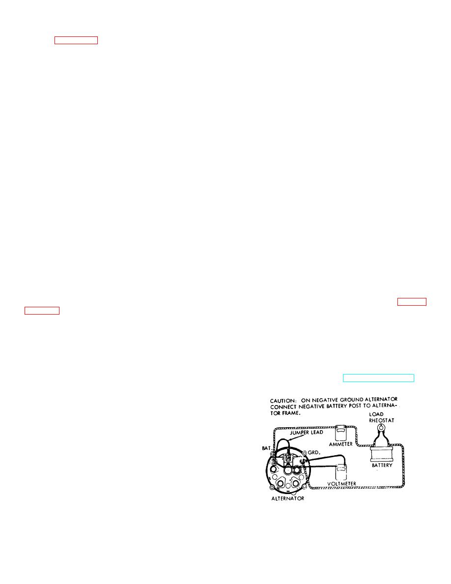
(1) Bench test. Bench test complete unit as
between each phase of the stator. If the bulb fails to
follows:
light, the stator is open and should be replaced.
(a) Make electrical connections as shown in
(4) Negative heat sink-rectifier test (fig. 3-3
). The negative heat sink is grounded to the housing by
(b) Operate alternator at 2000 rpm.
means of its mounting screws and stud. Be sure that
(c) Adjust load resistor for 27.5 to 28-volt
these screws are clean and tight so the negative heat
reading on voltmeter. If voltage is above or below this
sink makes good contact with the housing. Connect
reading, readjust by removing pipe plug from top of drive
negative lead of ohmmeter to test point one and touch
end housing and turning voltage adjusting screw with a
positive lead to terminals 4, 5, and 6. A high resistance
small screwdriver. Increase voltage by turning screw
reading should be obtained. If a low resistance reading
counterclockwise; decrease by turning screw clockwise.
is obtained, the diode is shorted and must be replaced.
Note. Be sure to replace plug after adjustments
g. Installation. Refer to TM 5-3810-28912 and
have been made, to keep out the dirt and moisture.
install the alternator.
(d)
The ammeter should read 55-60
amperes. A slightly low reading is an indication of an
open silicon rectifier. A considerably lower reading is an
indication of a shorted silicon rectifier. The latter is
usually accompanied by a hum or growling sound made
by the alternator.
(2) Rotor test. The rotor can be tested with
an ohmmeter and should read 7 to 7.8 ohms from slip
ring to slip ring.
Note. Slide the three insulating sleeves away from
the splices and unsolder the splices to disconnect rotor
from the rectifier.
(3) Stator test.
(a) Ground test. Connect a test light from
Figure 3-2. Alternator test connections.
each stator lead to the stator core or frame of alternator.
If the bulb lights, the stator is grounded and must be
replaced.
3-3


