TM 5-3810-289-34
(6)
Governor plunger.
Slide governor
(b)
Lift cap, spring and filter screen
plunger from barrel, figure 3-12.
assembly from main housing; discard performed
Caution: Place plunger where it will not be
packing. The screen assembly is made up of a screen,
damaged, a slight nick can cause extensive damage.
magnet and two retainers. The bottom retainer has a
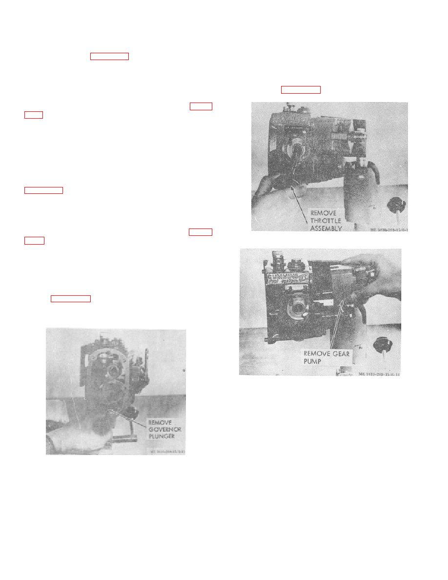
(7) Throttle assembly.
hole in center to permit fuel flow; this retainer is soldered
(a) Compress nameplate retaining ring and
to the screen, figure 3-17.
remove from groove.
(b) Pull throttle assembly from pump, figure
sizes are identified by color code.
Caution: Handle throttle shaft with care.
(8) Gear pump.
(a) Remove capscrews and lockwashers
securing gear pump to main housing.
(b) Tap side of gear pump with a plastic
hammer to loosen from dowels.
(c) Lift gear pump off and discard gasket;
(9) Governor spring-pack.
(a) Remove capscrews, lockwashers and
flat washers securing governor spring-pack cover to
main housing.
(b) Lift off cover and discard gasket, figure
Figure 3-13. Throttle assembly removal.
(c) Remove snap ring which holds governor
spring pack in sleeve with a pair of snap ring pliers.
(d)
Remove high-speed spring, spring
retainer and shims from spring-pack housing.
(e) Remove idle-spring plunger guide, idle
spring or springs, idle spring plunger, and spring rest
washer, figure 3-16.
(10) Filter screen cap.
(a) Loosen filter screen cover on top of main
housing.
Figure 3-14. Gear pump removal.
Figure 3-12. Governor plunger removal.
3-8


