TM 5-3810-289-34
Figure 3-106. Water pump, exploded view.
c. Disassembly.
(1) Remove capscrews (7, fig. 3-106) and
lock washers (14); lift cover (8) and gasket (10) from
pump body (3).
(2) Remove lock capscrew (4) from pulley
end of shaft.
(3) Pull sheeve (22) from shaft using ST-
647.
(4) Remove snap ring (19) from pump body
(3).
(5)
Support pump on body face near
bearing location; press shaft and bearings (21, 1, and 2)
from pump body (3) and impeller (11) toward drive pullley
end of body.
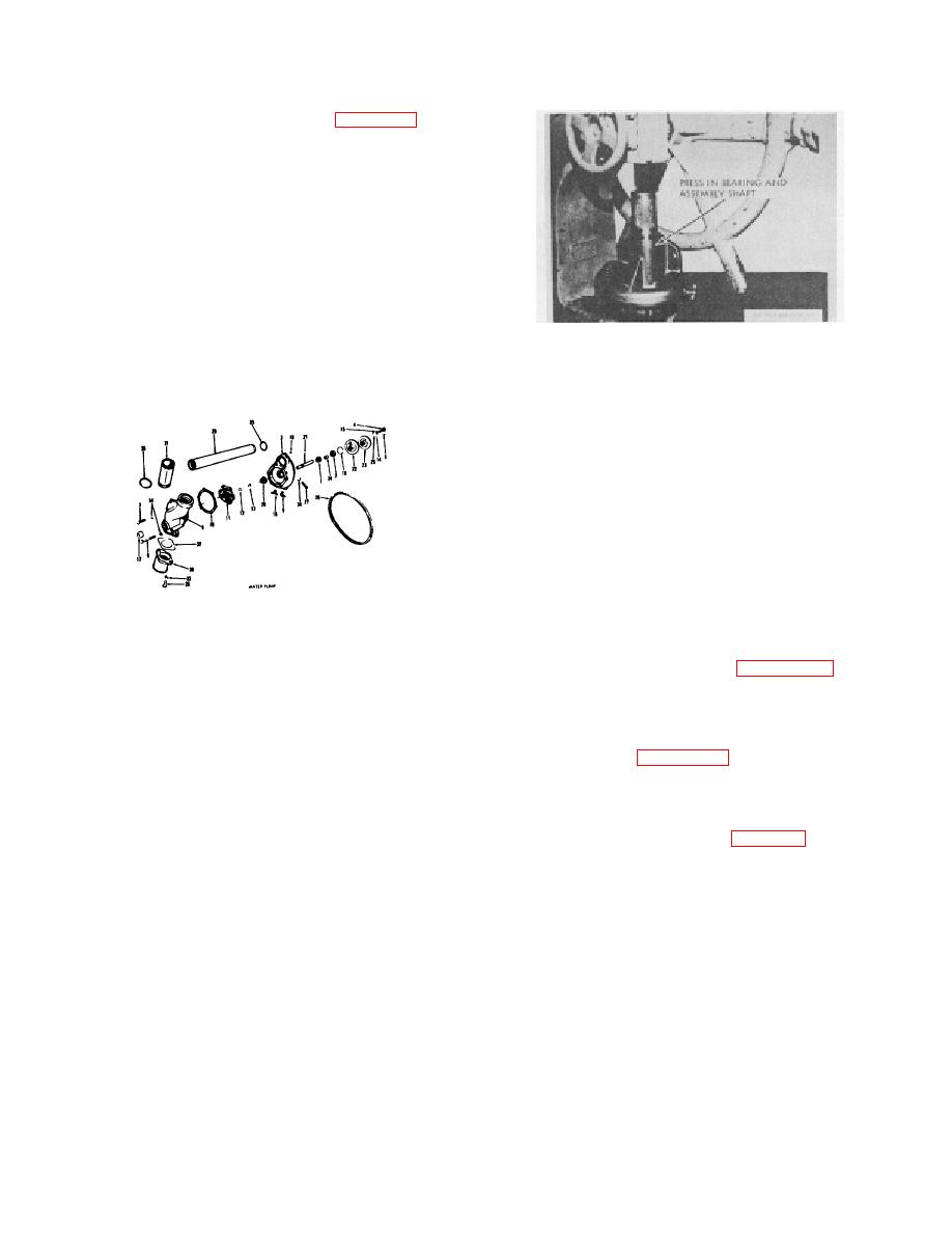
Figure 3-107. Bearing and shaft assembly being pressed in.
(6) Remove carbon face seal (20) from
d. Cleaning and Inspection.
body.
(1) Clean all parts in an approved cleaning
(7) Press two bearings (1 and 2) and spacer
solvent. Remove all rust, scale and corrosion from cover,
(24) from shaft (21).
body and impeller.
(2) Inspect shaft, impeller and pulley sheaves
for excessive wear or damage.
(3) Check shaft outside diameter in impeller
area. Shaft must be 0.001 inch or more larger than impeller
bore diameter. If interference fit between shaft and impeller
is less than 0.001 inch, discard impeller.
(4) Check ball bearings for rough or binding
operation, excessive looseness and worn or damaged
races.
(5) Examine carbon face seal carefully to see
1 Ball bearing
2 Ball bearing
that it is not cracked or chipped.
3 Pump body
(6) Discard all defective parts.
4 Screw , cap (7/16"-14x ")
e. Assembly.
S Screw, cap(5/16"--18 x 1)(3)
(1) Lubricate shaft (21, figure 3-106) be, fore
6 Screw, cap(S/16"- lSx )(2)
installing bearings.
7 Screw, cap (5/16"-18 x7/8")
8 Pump cover
(2) Press small bearing (1), spacer (24) al d
9 Flexible elbow
larger bearing (2) on shaft (21).
10 Gasket
(3) Support body on cover face: press in shaft
11 Impeller(122294)
and bearing assembly, figure 3-107.
12 Bonding film
13 Impeller eat
Note. Just prior to assembly, apply a thin coating of sealer
14 Washer, look (5/16") (9)
such as "Loctite" grade B or its equivalent (hearing mount J to I D.
15 Washer, lock (7/16"1
of housing, where bearing mounts Bearing C D. and housing I D
16 Drain eoek
must be free of grease and oil.
17 Pipe plug (i"
(4) Insert snap ring(l19, fig. 3-106f.
18 Pipe plug(l/8"i
Note. Current production water pump bodies are machined
19 Retaining ring
for beveled snap rings. Older models use flat snap ring, Replace
20 Pump seal
same type snap ring as removed. Flat and hexeled
rings are
21 Shaft
22 Fixed sheave
not interchangeable
23 Adjusting sheave
(5) Support housing on pulley end of body (3).
24 Spacer
(6) Apply lead pipe sealer such as Job, Crane
25 Washer, plain
Plastic Lead Sealer No. 2 or equivalent to carbon face seal
26 Belt
outside diameter that beats at bottom of bore.
27 Screw, cap(7/16"-14 x l'4"(3)
28 Screw, cap(3/8"-16x l"'(2)
(7) Locate body so carbon face seal (20) will
29 Connection
press squarely into its bore.
30 Inlet connection
(8) Press carbon face seal into pump body with
31 Bypass coupling
force applied on driving lip (flange on seal housing) (fog. 3-
32 Gket, connection
33 Washer, lock (8") (2)
108) of seal. Apply only enough force, to seat seal in
34 Washer, lock (7/16")(3)
housing bore.
35 Oringt4i
3-37


