TM 5-3810-289-34
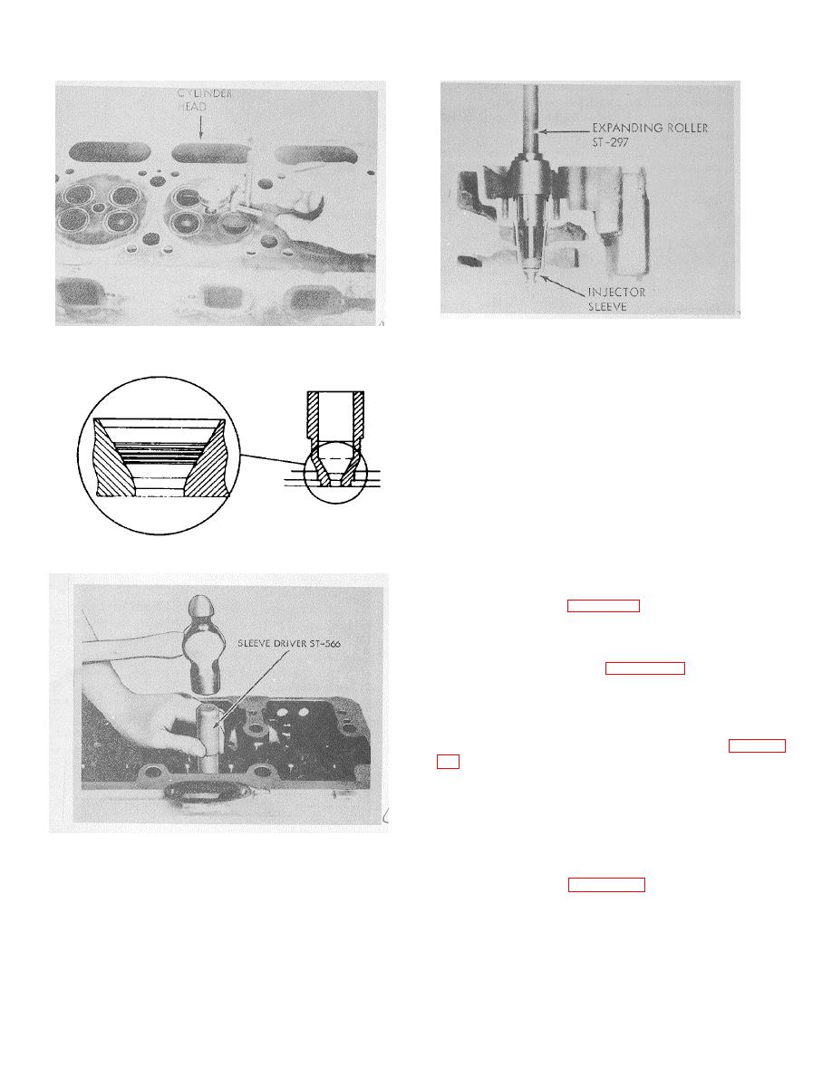
Figure 3-98. Sealing upper end of injector sleeve with
Figure 3-95. Measuring injector tip protrusion.
ST-297.
Caution: Do not cut more than 0.010 in. deep.
(6)
When the proper depth has been
obtained, allow the cutter to dwell for approximately 10
seconds to insure a good seat and clean grooves.
(7) Lubricate and install ST-825 Cutter,
adapter and ST-843 pilot. Attach a tap wrench to the
adapter and rotate, applying a light even pressure. The
ST-825 Cutter is used to cut a 30 degree angle chamfer
at the lower edge of the 60 degree seat. When the
upper end of the 30 degree angle chamfer is
approximately 9/64 inch from the bottom bead, remove
cutter, adapter and pilot.
Figure 3-96. Sleeve seat bead and chamfer location.
(8) Remove bluing from 60 degree seat.
d. Installation.
(1) Drive in injector sleeve with ST-566
injector sleeve driver, figure 3-97.
(2) Remove driver from injector sleeve and
install injector sleeve holding tool ST-923 or ST483.
(3) Seal upper portion of sleeves with
expanding roller, ST-297, figure 3-98. Apply force to
expand rollers until sleeve upper diameter reaches
1.375/1.380 in.
(4) Remove the injector hold down tool.
(5) Seal injector sleeve in lower seating
(tapered) area with Angle Roller Tool, ST-819, figure 3-
(6) With roller in drill press set at 250 rpm,
apply 500/650 lbs. axial force for 30 seconds. Lubricate
roller during this operation.
(7) Cut injector seat to provide proper
injector seat and injector tip protrusion. Use ST379
seating cutter and ST-379-2 pilot tool.
It is very
important that the cutter be ground to the exact
Figure 3-97. Installing injector sleeve.
dimensions shown in figure 3-100.
(8) To determine amount of cut, install
injector and measure tip protrusion. Depth of cut should
provide 0.040/0.055 inch protrusion of injector cup tip
beyond milled face of cylinder head. Maximum allowable
injector cup protrusion is 0.065 inch.
3-32


