(9) Replace swing and propel gear case front
(10) Fill gear case to proper level with lubricant
in accordance with the lubrication orders d. Adjustment.
Remove or add shims under spur gear retainer to secure
correct end play.
4-8.
Rear Drum Shaft Assembly
a. General.
(1) The shaft is alloy steel mounted on ball
bearings, with a 4" major diameter. Shaft speed is 37.6
R.P.M. with diesel engine direct drive at full load speed.
(2) Hoist and swing gears are heat treated
steel castings with machine cut teeth. Hoist gear is keyed to
the shaft. Swing gear is keyed to the swing clutch housing.
(3) Swing clutch housing is mounted on ball
bearings.
(4) There is a plain tapered rope drum with
integral clutch and brake housing mounted on ball bearings.
(5) The drum brake is an external contracting
band type, 27'" diameter; 3" wide-and mechanically
operated.
(6) The drum clutch is an internal expanding
band type, 24" diameter; 3" wide and mechanically
operated.
(7) The clutch on right side of rear shaft is
used to power controlled load lowering of crane hoist line.
Housing is grooved on outer surface for cooling. The clutch
is mounted on ball bearings.
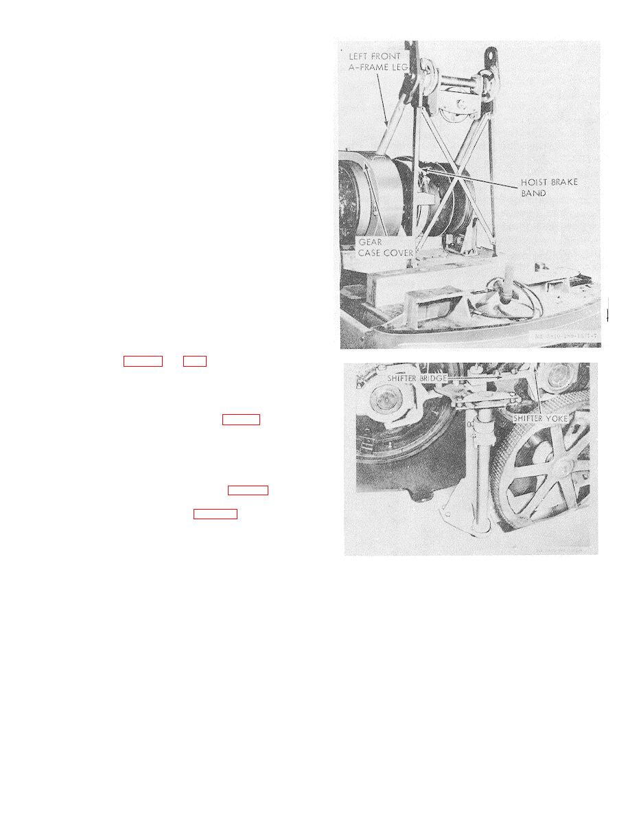
Figure 4-9. Rear drum shaft removal.
(1) Lower boom to rest securely and slacken
suspension ropes.
(2) Remove hoist rope from drum.
(3) Remove left front A-frame leg, first
removing left front and center cab sections (fig. 2-2') if shaft
is to be lifted out with crane. If removal is to be handled
manually, shaft can be partially stripped and skidded out
through left door without removing A frame leg or cab
sections.
(4) Remove retract clutch guard.
(5) Remove hoist brake band. (fig. 4-9.)
(6) Remove retract and swing clutch shifter
yokes and hoist clutch shifter screws (fig. 4-10).
(7) Remove shifter lever bridge.
(8) Remove right and left bearing housings,
which are attached by two bolts in each.
Note. Be careful not to mix right and left
Figure 4-10. Re drum shift shifter bridge and yoke.
bearing bolts m right bolts are drilled to receive clutch
(11) If no crane is available and shaft must be
guards.
removed manually, further dismantling in Race is advisable
(9) Remove gear case cover.
in order to reduce weight.
See shaft disassembly
(10) The entire assembly, weighing about 1200
instructions in following paragraphs.
c. Disassembly
After
Disconnecting
and
pounds can now be lifted out if crane is available.
Removing Shaft From Machine.
The following
Caution: Do not move the assembly
subassemblies remain on the shaft after carrying out the
horizontally until the gears are clear of the cue.
instructions in paragraph a. If shaft is to be removed
manually, these should be disassembled as far as possible
before and during raising of shaft following stripping
directions as given below and in following paragraph. If a
crane is used, these assemblies can be removed with the
shaft and later disassembled as required.
(1) Rear swing-and-propel clutch.
4-11


