to figure 4-11 and disassemble shaft as required to remove
Disconnect controls and remove bracket for convenient
the hoist clutch.
access to shaft.
4-10. Front Drum Shaft Assembly
a. General. The shaft is alloy steel mounted on
ball bearings with a 4 1/8" major diameter. Shaft speed is
37.1 R.P.M. with diesel engine direct drive at full load
speed.
(1) Hoist and swing gears are heat treated
steel castings with machine cut teeth. Hoist gear is keyed to
shaft. Swing gear is keyed to swing clutch housing.
(2) Swing clutch housing is mounted on ball
bearings.
(3) Boom hoist drum is located inboard of left
machinery side frame. It is mounted on ball bearings.
Clutch and brake housing are cast integral with the drum.
(4) Boom hoist brake is external contracting
band type, spring set and released with boom hoist control
lever. It has 24" diameter and is 2 1/2" wide.
(5) Boom hoist clutch is internal expanding
band type, set by a booster clutch band. It is mechanically
controlled, 20" in diameter and 2" wide.
(6) Boom hoist clutch driver is keyed to the
shaft.
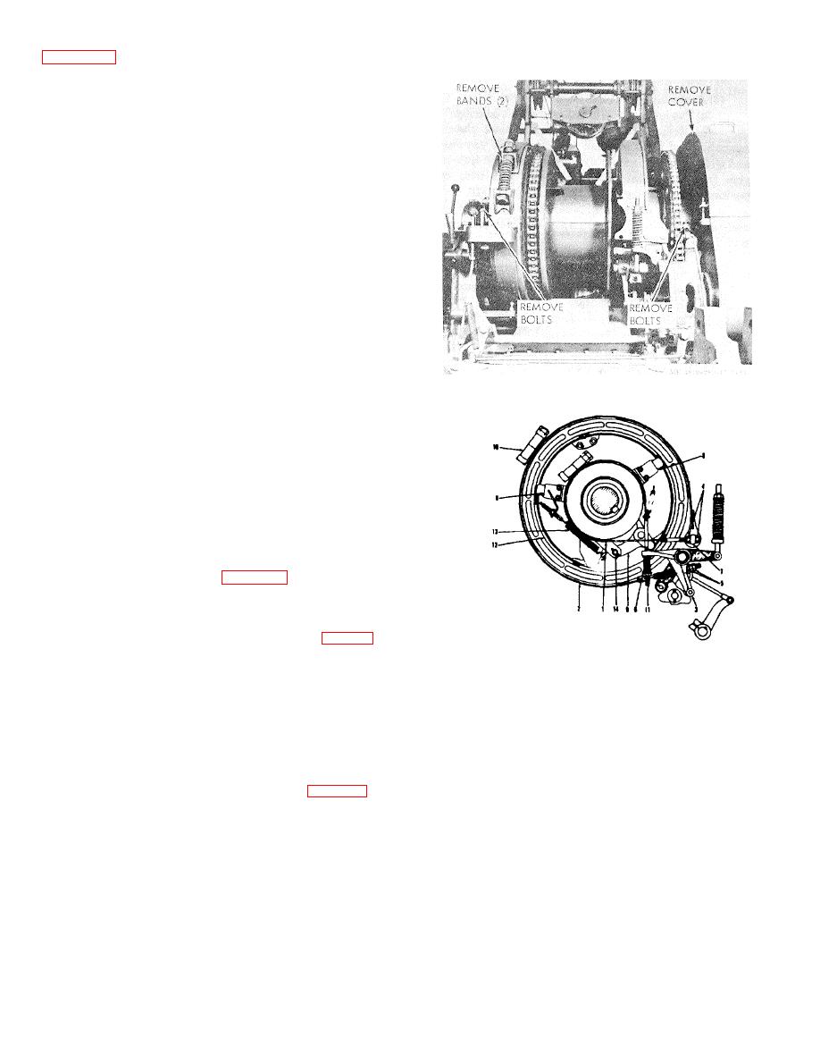
Figure 4-15. Front drum shaft removal.
(7) Front rope drum clutch housing is cast
integral with brake and clutch housing. It is mounted on ball
bearings.
(8) Drum brake is external contracting band
type, 27 1/2" in diameter, 3" wide and mechanically
operated.
(9) Drum clutch is internal expanding band
type, 24" in diameter, 3" wide and mechanically controlled.
(10) Forward and below the front drum shaft is
a countershaft which contains the mechanism for power
controlled lowering of the boom hoist.
b. Removal. Refer to figure 4-15.
(1) Lower boom to rest securely, slacken
suspension ropes, and remove rope from boom hoist drum.
(2) Remove left front A-frame leg.
(3) Remove left front cab sections (fig. 2-2) if
Figure 4-16. Boom hoist clutch and brake band removal
lifting shaft with crane. If handling manually, shaft can be
and installations.
partially stripped and skidded out through left door.
1
Booster band
8 Band guides
(4) Remove clutch and boom hoist guards.
2
Brake band
9 Main clutch bell crank
(5) Remove boom hoist speed control chain
3
Booster band cam roller
10 Booster bond joint bolt
(disconnect at any link) and safety pawl control rod.
4
Booster band clutch adjusting nuts
11 Cushion spring nut
(6) Remove boom hoist brake and booster
5
Brake band adjusting nuts
12 Main clutch band
bands.
6
Cushion spring
13 Clutch release spring
7
Dead end pin
14 Cotter pins
(7) If front rope lagging is on, remove rope
guard at the drum flange.
nect controls and remove bracket for convenient access to
(8) Remove retract brake band. (fig. 4-16).
shaft.
(9) Remove clutch shifter yokes by first
(11) Remove bolts from right and left bearing
removing integral head plate and yoke pin and the two yoke
housings.
screws on each at the collar ends.
Note. Be careful not to mix up right and left
(10) Remove two long horizontal bolts
bearing housing bolts as right bolts are drilled to
supporting lever bracket on right hand bearing housing.
receive clutch guards.
(12) Remove gear case cover.
(13) The entire shaft assembly, weight about
1200 pounds, can now be lifted out if crane is available.
Caution:
Do not move the assembly
horizontally until it has been lifted far enough so the
gears are out of the case.
4-18


