(8) Assembly operations from the right.
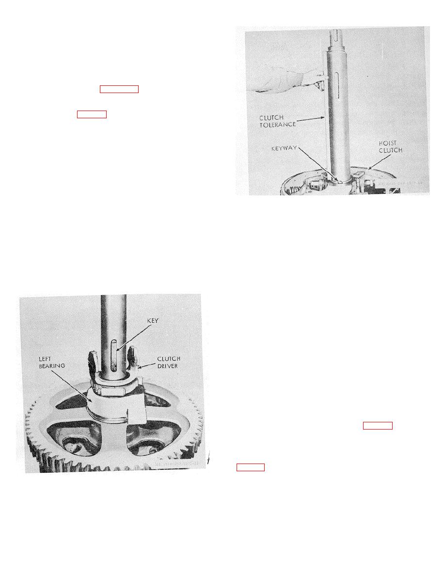
(a) Tap left bearing housing over left
bearing.
(b) Remove clutch driver from hoist
clutch assembly and slide on shaft. Insert key in keyway
mad slide on clutch assembly by wedging split hub to give
free movement. Remove wedge and lock in position by
tightening driver bolt. See figure 4-18.
(c) Check distance between bearing
facing lip and uppermost part of clutch. Allowable tolerance
is 257/16" 1/32" (fig. 4-14).
(d) Tap left drum bearing into position
with shield side against driver.
(e) Put combination drum and clutch
housing on shaft and drive it into place on left bearing. Pack
cavity half-full with GAA wheel bearing grease.
(f) Tap right bearing into position in right
end of drum with shield outermost.
(g) Slide spacer into place.
(h) Tap on the inner bearing of the
secondary hoist clutch housing and sprocket with shield side
Figure 4-14. Rear drum shaft assembly.
next to spacer.
lock into place.
(i) If sprocket has been removed from
Note. In assembling part all across the shaft
hub of housing replace it using 20-to 30-ton press.
from the main drum clutch driver to secondary hoist
(j) Slide housing with sprocket into
clutch driver, seat each part solidly against the part
place and tap into position on inner bearing. Pack cavity
ahead of it. When the secondary hoist friction clutch
halffull with GAA wheel bearing grease.
driver has been thus seated, back it off 1/32 inch before
(k) Insert outer bearing and tap it into
clamping in place on shaft to provide a free running fit
place in hub with shield side outermost.
for all parts across right side of shaft.
(l) Insert driver key in keyway and slide
(n) Tap right shaft bearing into right
clutch assembly into place wedging split hub to permit free
bearing housing (shield side inside) solidly against shoulder.
movement. Driver key must not protrude from driver hub.
(o) Tap assembly of bearing and
housing on shaft, open side (on cover side) of housing
outermost.
(p) This completes assembly operations
from the right.
g. Installation.
(1) Lower shaft into place, carefully matching
bearing housing and their shear pins.
(2) Bolt housings in place.
(3) Install gear case cover.
(4) Assemble three main clutch shifter yokes.
(5) Install rear drum brake band and connect
brake lever.
(6) Install clutch guard and left front A-frame
leg.
(7) Reeve hoist rope on drum.
(8) Replace cab section. (fig. 2-2).
(9) Drain and replace transmission case
lubricant in accordance with lubrication order.
h. Complete Shaft Installation and Connections.
(1) Replace left side and front corner of cab.
(2) Reassemble secondary hoist clutch band.
Figure 4-13. Rear drum shaft assembly (right side).
(3) Reassemble rear hoist drum clutch.
(4) Reassemble swing-and-propel clutch.
4-9.
Hoist Clutch
For disassembly procedure of the hoist clutch refer
4-17


