SECTION VIII
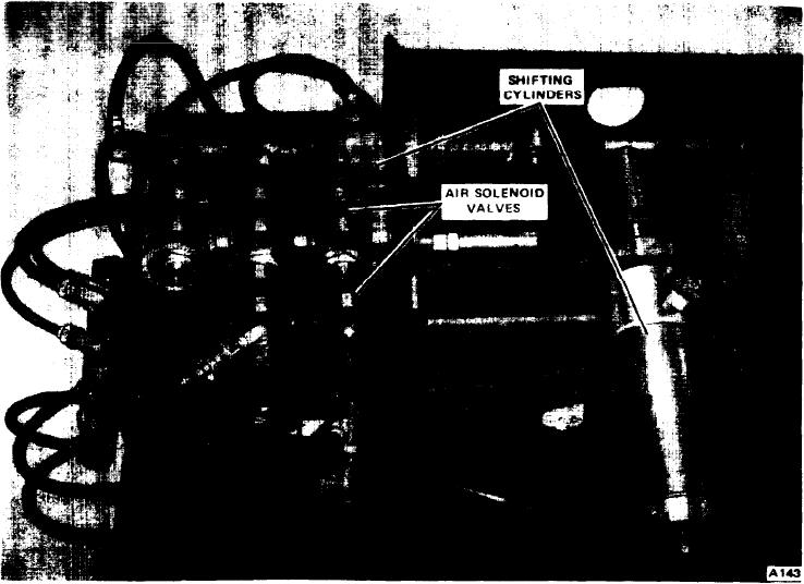
Figure 8-2. Remote Control Assembly
1. Make a check to see that all wiring, hoses and con-
15. Remove the two front mounting bolts and the four
nections are clear of the mountings and frame.
rear mounting bolts. which hold the engine to the carrier
frame. Also, remove the bolt supporting the main trans-
2. With suitable lifting device, lower engine and main trans-
mission.
mission into the carrier.
16. Remove the engine from the carrier. Do not lose the
3. Place the mounting insulators, two at the front of the
mounting insulators on the frame.
engine and two on each side at rear of the engine. Place
insulators between carrier frame and engine mountings.
REPAIRS AND ADJUSTMENTS. Engine repairs and
4. Install the engine mounting bolts and tighten.
adjustments are covered by a Service Manual prepared by
the engine manufacturer. These service manuals can be
5. Place the radiator insulators on the frame. Install
obtained by contacting the nearest engine dealer or from
radiator and fasten to the frame.
the manufacturers at the following addresses:
6. Install the exhaust pipe.
Detroit Diesel Engine Division
General Motors Corporation
7. Connect all the electrical wiring that was disconnected
13400 W. Outer Drive
to remove the engine.
Detroit. Michigan 48228
8. Connect all the hydraulic and air hoses that were discon-
Cummins Engine Co., Inc.
nected to remove the engine.
1000 Fifth Street
9. Replace the upper and lower radiator hoses.
Columbus, Indiana 47201
10. Connect the clutch linkage and shift rod.
INSTALLATION. To install the engine. clutch and main
transmission in the carrier, proceed as follows:
11. Connect propeller shaft to main transmission.
8-2

