
SECTION VIII
12. Install pump drive propeller shaft.
13. Install air cleaner bracket, air cleaner and hose.
14. Install fuel filter bracket and fuel filters on the engine.
15. Connect the fuel lines to the filters.
16. Fill the engine with oil and water. Check transmission
oil level, and add oil as needed.
17. Replace the sheet metal.
18. Run engine and check for oil, water, and air leaks.
ENGINE CLUTCH (1524451
REMOVAL. To remove clutch from engine, the main
transmission must first be removed, as described under the
topic Main Transmission. After the main transmission has
been removed proceed as follows.
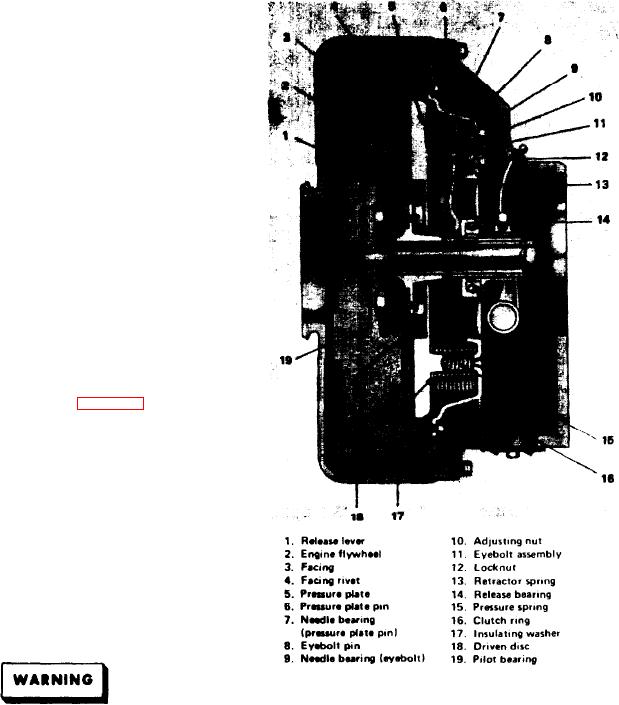
1. Loosen the clutch ring mounting screws diagonally
opposite each other a little at a time to relieve the spring
force on the clutch ring rim (see Figure 8-3).
2. Matchmark the engine flywheel, clutch ring, and pres-
sure plate so that they can be reassembled in their original
position. This is important since they are balanced as an
assembly. Matchmark the driven discs on engine flywheel
side to prevent installing them in the reversed position.
DISASSEMBLY. To disassemble the engine clutch,
proceed as follows:
1. Place the clutch assembly, with the ring upward on the
bed of an arbor press. Place a steel bar across the top of the
clutch ring, and press down to relieve spring pressure on the
clutch ring. Remove the locknuts.
Figure 8-3. Engine Clutch Assembly
Use extreme caution when releasing the clutch as-
sembly since the pressure springs are compressed
when the clutch is assembled.
A. The hub splines are worn.
2. Release the pressure on the clutch ring. Remove the
B. The disc is distorted.
clutch ring, pressure springs, and insulating washers.
C. The disc is cracked or broken.
3. Remove the retaining rings and pressure plate pins.
2. If the driven disc friction material is worn excessively,
Remove the release lever assemblies, eyebolt assemblies,
replace the material. Refer to the Replacement Parts
and adjusting nuts.
Manual. Use a star set anvil when riveting fabric facings, a
roll set when riveting metallic facings.
REPAIR AND INSPECTION. After the clutch has been
3. Replace the pressure plate if any of the following con-
disassembled, clean all parts thoroughly end inspect the
parts for wear. Check the following items:
ditions are present:
1. Replace the driven disc assemblies if any of the fol-
A. The friction surface of the pressure plate is severely
lowing conditions exist:
heat checked.
8-3