
SECTION VIII
REPAIR. Repair of the propeller shaft is limited to replace
Insert the bearings from the outside of the yoke. Press or
ing the journal cross, bearings, and snap rings. To replace
tap the bearing into place with a soft drift punch.
the bearing assemblied, proceed es follows:
3. Install lock straps (2) and capscrews (1).
1. Remove snap rings (2) and bearings (3).
INSTALLATION. To install the propeller shaft, proceed as
2. Tilt journal cross (4) to one side and remove it from the
follows:
yoke.
1. Lubricate the other set of bearings with multipurpose
grease. Insert the bearing from the outside of the yoke.
NOTE
Press or tap the bearings into place with a soft drift punch.
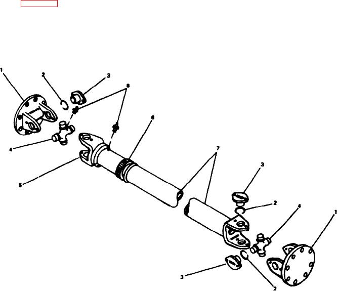
If slip joint (6) is removed from shaft (7), they must
2. Install lock strap (2) and capscrews (1).
be reassembled in the same position. The met&-
marking arrows on the shaft and sleeve must be
PROPELLER SHAFT (20Q17)
visible before disassembly. If the arrow marks are not
GENERAL. This propeller shaft is used to connect the
visible, mark both members before disassembling
pump drive to the front of the engine.
thorn.
The slip joint end of the propeller shaft must always be
ASSEMBLY. To assemble the bearing assemblies, proceed
installed nearest the power source, The slip joint allows for
as follows:
variations in the Iength of the propeller shaft caused by
1. Tilt journal cross (4) and insert it in the yoke.
movement of the connected units.
2. Lubricate one set of bearings with multipurpose grease.
REMOVAL. To remove the propeller shaft, proceed as
Insert the bearing from the outside of the yoke. Press or tap
follows (see Figure 8-11):
the bearing into place with a soft drift punch.
1. Remove the bolts securing the companion flange, to the
3. Install snap rings (2).
flange yoke at each end of the shaft.
INSTALLATION. To install the propeller shaft, proceed as
2. Lower the propeller shaft from the carrier as a complete
follows:
unit.
Figure 8-11. Propeller Shaft (20Q17)
8-9