AIR SYSTEM COMPONENTS
SUE-SECTION 9C
TEST OF REBUILT SAFETY VALVES. Both the opera.
ting and Ieakage test must be made after repairing the safe-
ty valve and the valve must meet the following specifica-
tions:
1. Leakage at the exhaust port should not exceed a three-
inch soap bubble in three seconds.
2. The safety valve should be set to "blow off" at approxi.
mately 150 pounds (10.34 BARS). The pressure setting
may be adjusted by loosening the locknut and turning the
adjusting screw. Turning the adjusting screw clockwise,
raises the pressure setting. Turning the adjusting screw
counterclockwise. lowers the pressure setting. The setting
of the adjusting screw should be locked by tightening the
adjusting screw locknut after each adjustment. An accurate
test gauge should be used when adjusting pressure setting of
the safety valve.
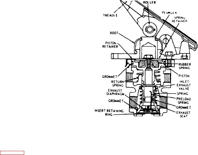
TREADLE VALVE (36Z225)
DESCRIPTION. The treadle valve is the control unit of the
air brake system. It provides the driver with an easily oper-
Figure 9C-3. Treadle Valve (38Z225)
ated and graduated means of applying or releasing the ve-
OPERATING TEST. Check the delivery pressure of the
hicle brakes.
treadle valve using a test gauge known to be accurate. De
press the treadle to several positions between the fully re-
When the treadle IS pressed down by the driver's foot, force
leased and fully applied positions and check the delivered
IS exerted on the plunger, rubber graduating spring and to
pressure to see that it varies proportionately with the move.
the piston (see Figure 9C-3). The piston moves down and
ment of the treadle. When the treadle is fully applied the
its stem which is the exhaust seat closes the exhaust. As the
reading on the test gauge should be approximately that of
exhaust closes. the inlet valve moves off its seat. Air pres-
full reservoir pressure. The reading on the test gauge should
sure from the reservoir then flows in by the inlet valve and
fell off to zero when the treadle is released.
out the delivery port to the brake actuators.
LEAKAGE TEST. With the valve fully released, check the
When the air pressure in the cavity beneath the piston and
exhaust port for leakage. No leakage is permissible. Make
the air pressure being delivered to the brake actuators
and hold a high pressure application. Coat the exhaust port
equals the mechanical force on the top of the piston, the
and the top of the valve with soap suds. No leakage is
piston lifts and the inlet valve closes, cutting off any further
permissible.
flow of air from the supply line through the valve. The
exhaust remains closed, preventing any escape of air
If the treadle valve does not function as described above, or
through the exhaust port.
leakage is excessive, it is recommended that the complete
valve be replaced. If it is desired to rebuild the treadle valve,
When applications in the above average pressure range are
contact the nearest Bendix-Westinghouse distributor for
made, the valve reaches a balanced position as the air pres-
overhaul information and parts.
sure beneath the piston equals the effort exerted by the
driver's foot on the treadle. When the piston is pressed
NOTE
down all the way, the inlet valve remains open and reservoir
pressure is delivered to the actuators.
The inlet end exhaust valve assembly, generally re-
ferred to as the E-2 insert. can be removed end re-
If the treadle application is released and mechanical force is
placed without disturbing the valve mounting or its
removed from the top of the piston, the air pressure be-
connections. Contact a Bendix-Westinghouse distribu-
neath the piston is then greater end the piston lifts, opening
tor for further information on the insert. Before
the exhaust in the valve. The air below the piston and in the
removing the insert, it is important that the air sys-
delivery lines is then exhausted through the exhaust port.
tem be drained.
9C-4

