SUBSECTION SC
AIR SYSTEM COMPONENTS
passage in the relay valve. exhausting air pressure from the
RELAY VALVE (36Z291)
brake chambers through the relay valve exhaust port.
DESCRIPTION. The relay valve serves to speed up the
OPERATING AND LEAKAGE TEST. To determine the
application and release of the rear wheel brakes. The valve
serviceability of the relay valve, perform the following test:
operates as a remote controlled brake valve, delivering air
pressure directly from the reservoir to the brake chambers,
1. Fully charge the air system.
at a rate proportional to the pressure delivered to the front
2. Make several brake applications and check for prompt
brake chambers by the treadle valve.
application and release of all rear wheel brakes.
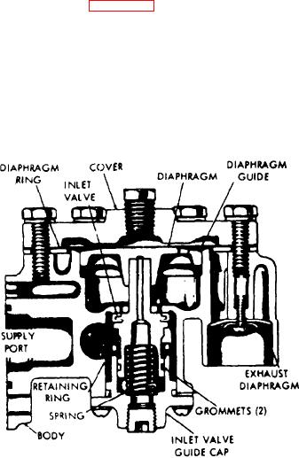
The relay valve (see Figure 9C-5) operates very rapidly be-
3. With the treadle valve in the fully released position, coat
cause of the small volume of air required to fill the space
the exhaust port of the relay valve with soap suds. A maxi-
between the cover and diaphragm. When the treadle valve is
mum leakage of a one inch soap bubble in not less than
depressed, air pressure is delivered to the relay valve and
three seconds is permissible.
enters the relatively small cavity above the diaphragm. The
pressure developed in the cavity depresses the diaphragm
4. Make and hold a brake application. Coat the exhaust
and seals it against the exhaust seat. At the same time, it
port of the relay valve with soap suds. A maximum leakage
moves the diaphragm guide down and opens the inlet valve,
of a one inch soap bubble in not less than two seconds is
permitting air to flow from the dry tank through the relay
permissible.
valve, and to the brake chambers.
5. If the relay valve does not function as just described, or
leaks excessively, it is recommended that the valve be re-
placed. If overhaul of the valve is desired, contact the near-
est Bendix-Westinghouse distributor for overhaul informa-
tion and parts.
NOTE
The valve assembly, generally referred to as the R-5
insert, can be removed and replaced without re-
moving or disconnecting the lines attached to the
valve. Contact the nearest Bendix-Westinghouse dis.
tributor for information on the insert.
REMOVAL. To remove the relay valve, proceed as follows:
1. Block or hold the vehicle with wheel chocks.
2. Open the drain cock on each reservoir to drain the air
pressure from the system.
Figure 9C.5. Relay Valve (36Z291)
3. Disconnect the air lines attached to the relay valve.
As the air pressure below the diaphragm equals that above
the diaphragm, the inlet valve returns to its seat (balanced
4. Remove the mounting bolts, and then remove the valve.
condition) and the brake application is held at whatever
pressure the operator desires. A relief slot in the bottom of
INSTALLATION. To install a new or rebuilt relay valve,
the diaphragm guide permits air pressure to enter the cavity
proceed as follows:
below the inlet valve piston through the drilled hole in the
valve stem, thus assuring a positive balance of air pressure
1. Clean or replace the air lines connected to the relay
above and below the diaphragm.
valve. Replace any damaged air lines.
2. Mount the relay valve and secure it in place with the
When the treadle valve is released, the air pressure in the
mounting bolts,
cavity above the diaphragm and the connecting line is ex-
hausted through the exhaust port of the treadle valve. When
3. Test the valve for serviceability as outlined in Oparating
this occurs, the air pressure below the diaphragm moves the
diaphragm and diaphragm guide up, opening the exhaust
and Leakage Test.
9C-6

