POWER STEERING PUMPS
SUB-SECTION 10B
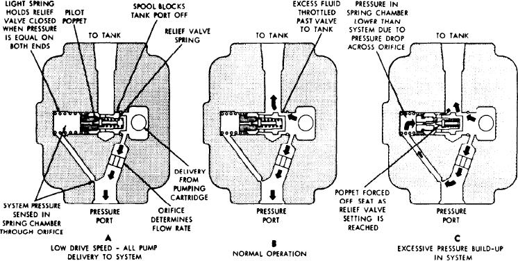
Figure 10B-2. Relief Valve Operation
4. Plug the ports of the pump and cap all lines to prevent
from the rotor, and remove the rotor from the drive shaft.
the entry of dirt into the system.
4. The following steps should be performed on/y if the seal
kit is to be installed. If the seal kit is not being installed,
5. Remove the drive belts.
proceed to step 5.
6. Remove the nut on the pump shaft and remove the
A. Turn the pump body over and remove the shaft key,
pulley with a suitable puller.
and the snap ring.
7. Remove the pump mounting bolts, and remove the
B. Tap with a soft hammer on the splined end of the
pump.
driveshaft to force the shaft out of the body.
C. Pull the shaft seal out of the body with a suitable
CARTRIDGE REPLACEMENT
hooked tool.
GENERAL. It is recommended that rebuild of this pump
5. Remove the plugs on each side of the cover, and remove
be limited to the replacement of the pumping cartridge
the spring and relief valve sub-assembly. Do not remove the
and/or seals, each of which is available in the form of a
snap ring unless it is damaged.
service kit.
INSPECTION AND REPAIR. Inspect and repair the fol-
Both kits contain the O-rings used to seal the sections of
lowing items:
the pump. Therefore, if both of these kits are installed at
the same time, one set of O-rings is not required.
1. Discard all O-rings and the shaft seal, if the shaft seal has
DISASSEMBLY. To install the service kits, disassemble the
been removed. Wash the metal parts in mineral oil solvent,
pump as follows (see Figure 10B-3):
blow them dry with filtered compressed air and place them
on a clean surface for inspection.
Scribe matchmarks on the cover, ring and body to en-
1
sure that the pump is reassembled with the inlet and dis-
2. Check the wearing surfaces of the inlet body and pres-
charge ports in the proper locations.
sure plates for scoring and excessive wear. Remove light
2. Clamp the pump body in a vise (not too tight), cover
score marks by lapping. Replace any heavily scored or
end up, and remove the four cover screws. Lift off the
badly worn parts.
cover and O-ring.
3. Check the bearings for wear and looseness. Rotate the
3. Remove the pressure plate and spring, and note the posi-
bearings while applying pressure to check for pitted or
tion of the cam ring for correct reassembly. Lift off the
cracked races.
cam ring and remove the locating pins. Separate the vanes
10-11

