TM 5-3810-294-34
(c) Install oil seal (2) in drum (461.
lifting device, attach a lifting sling to the boom foot lugs
on the revolving frame and to the gantry peak pin.
Pack seal with type GAA grease and be sure the sealing
Remove the upper from the carrier and place it on
lip points inward as shown in figure 2-11.
(d) Position drum (4) on drum (46).
suitable blocking, at least 3 feet above the ground to
provide adequate working room beneath the revolving
Install pinions (1) in drum (4).
(e) Lubricate O-rings (3) and install
frame.
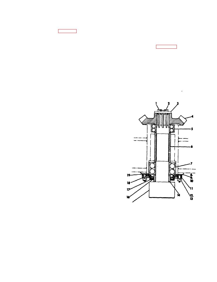
(3) Refer to figure 2-12 and remove the
them on pinion pins (48). Install pins (48) in pinions (1)
vertical swing shaft as follows:
Turn the pins so that the flats on the outer ends the pins
(a) Block shaft from below so that it
allow bearing retainer (5) to be installed. Install oil seal
(7) in bearing retainer (5). Be sure the sealing lip points
cannot fall.
(b) Remove six nuts (12) and six
inward, and pack the seal with type (GAA grease as
described in the current LO.
lockwashers (13) and remove retainer (11).
(f) Warm and install bearing (47) on
(c) From above, break lockwire (2)
the elongated hub of hub and gear (11). Warm an install
and remove two capscrews (1) and washer (3).
(d) Carefully remove blocking from
bearing (6) on the opposite end of hub and gear (11).
Install O-ring 19) on hub and gear (11)
beneath the shaft and remove shaft through bottom of
(g) Install hub and gear (11) with
the revolving frame. If may be necessary to bump the
shaft from above to start it out of gear (4).
bearings (47 and 6), and O-ring (9) into drum (46) as an
assembly.
(h) Install retainer (5) with grease
fitting (12) in place in the retainer, and secure retainer
with six capscrews and lockwashers (13 and 14).
(i) Carefully slide spacer (8) into
position against bearing (16).
(j) Using a suitable hoist, lift the
assembled drum and install it as an assembly on the
right end of shaft (10, FIG. 2-11).
(12)
Refer to TM 5-3810-294-20 and
perform the following operations:
(a) Install boom hoist brake band and
adjust as instructed.
(b) Install boom hoist clutch and
adjust instructed.
(c) Open hydraulic reservoir shut-off
valve
(d) Bleed hydraulic lines to the boom
hoist clutch and boom hoist brake.
(e) lnstall rear drum chain case and
the rear drum drive chain and adjust chain tension as
instructed.
(f) Adjust horizontal swing shaft chain
tension; be sure chains are properly mounted on all
sprockets before tightening eccentric adjusting shafts.
Reinstall the cover which provides access the chains.
Note. Be sure to prevent hydraulic fluid from
coming into contact with brake clutch linings during any
repair procedure.
1.
Capscrew 8.
.Shim
14. Spacer
2-21.
Vertical Swing Shaft
2.
Lockwire
9.
Shim
15. Pinion shaft
3.
Washer
10.
Shim
16. Oilseal
a.
Removal
4.
Gear
11.
Retainer
17.Bearing
(1)
Refer to TM 5-3810-294-20 and
retainer
perform the following operations:
5. Bearing
12. Nut
18. O-ring
(a) Remove front end attachment.
6. Spacer
13. Lockwasher
19. Gasket
(b) Remove hook rollers.
7. Bearing
(c) Drain main upper gear case oil.
(d) Remove one horizontal swing
Figure 2-12. Vertical swing shaft, removal and
shaft either left or right.
installation.
(2) Using a suitable overhead crane or
other
2-32


